
1. Purpose
In accordance with the Indian Constitution, national policies and international obligations, this standard identifies design requirements to ensure a certain minimum level of thermal comfort performance in residential developments with specific emphasis on low-income housing that have limited means/access to mechanical comfort systems. These requirements are based on adaptive thermal comfort. This standard further introduces design requirements for meeting progressively improved levels of thermal comfort. These further requirements would also prepare buildings for the potential use of active thermal comfort systems, to enable their operation at low energy use.
2. Scope
2.1 Scope by building typology
This standard applies to buildings used for residential purpose. The NBC defines residential buildings as those in which sleeping accommodation is provided for normal residential purposes with or without cooking or dining or both facilities. For the purpose of this standard, residential typology includes, and is not limited to, ‘One or two family private dwellings’, ‘Dormitories’ and ‘Apartment Houses’ . Specific exclusions to this standard include ‘Lodging and rooming houses’, ‘Hotels’, ‘Starred Hotels’ and residential facilities in Institutional Building typologies such as ‘Hospitals and sanitoria’, ‘Custodial institutions’, and ‘Penal and mental health institutions’.
2.2 Building status
This is a design standard applicable to building/s in the design stage, or building/s undergoing additions or alterations. This standard is applicable to the whole building. In the case of additions and/or alterations, compliance shall be demonstrated for the whole building. The standard is not applicable to parts of the building.
2.3 Building components
This standard includes requirements for the building envelope, low energy cooling/heating systems, and lighting fixtures.
2.4 Performance scope
This standard identifies three progressive grades of thermal comfort performance; Level A, Level A+ and Level A++. In order of performance, Level A provides a minimum level of thermal comfort and Level A++ is the most comfortable.
2.4.1 Minimum level of thermal comfort performance
2.4.1.1 Mandatory requirements outlined in sections §4.3.1 must be met with for all compliance levels.
2.4.1.2 To demonstrate compliance with this standard, it is mandatory to meet Level A, or better performance.
2.4.1.3 In case any building uses mechanical space conditioning systems, it is mandatory to meet Level A++ performance for demonstrating compliance with this standard. In context of this requirement, mechanical space conditioning equipment does not include ceiling/wall/table and exhaust fans, and desert/swamp coolers.
2.4.2 Thermal Comfort performance levels
Based on desired comfort, the design may opt for either of the following thermal comfort performance levels.
- Level A (Minimum level of Thermal Comfort Performance) compliant building
To demonstrate compliance with Level A, the design must demonstrate Level A performance or better, by following the provisions outlined in Section §4.3.2 Prescriptive approach or Section §4.3.3 Bundle approach. - Level A+ compliant building
To demonstrate compliance with Level A+, the design must demonstrate Level A+ performance or better, by following the provisions outlined in Section §4.3.2 Prescriptive approach or Section §4.3.3 Bundle approach. - Level A++ compliant building
To demonstrate compliance with Level A++, the design must demonstrate Level A++ performance or better, by following the provisions outlined in Section §4.3.2 Prescriptive approach or Section §4.3.3 Bundle approach.
2.5 Precedence
The following codes, programs, and policies will take precedence over the Code in case of conflict:
- Any policy notified as taking precedence over this Code, or any other rules on safety, security, health, or environment by Central, State, or Local Government.
- Bureau of Energy Efficiency’s Eco-Niwas Samhita (Parts 1 & 2), Standards and Labels for appliances and Star Rating Program for buildings, provided these or either are more stringent than the requirements of this standard.
2.6 Reference Standards
This standard refers National Building Code of India 2016 (NBC), Model Building Bye Laws 2016, Energy Conservation Building Code 2017 (Amended 2020), Eco-Niwas Samhita (Parts 1 & 2) and Bureau of Energy Efficiency’s Standards and Labels for appliances.
In addition, national and international standards for various test procedures have been referenced.
3. Thermal comfort evaluation and compliance approach
Indoor Operative Temperature is a simple thermal comfort index that is utilized by the Adaptive Comfort approach to quantify thermal comfort. This index takes into account; the air temperature, mean radiant temperature and air speed . The adaptive comfort model used for developing this standard uses the operative temperature to define a range of temperature which is considered comfortable.
This standard uses Degree Discomfort Hours (DDH) calculated over the Indoor Operative Temperature as the thermal comfort performance metric. The various provisions of this standard are designed to effect a reduction in Degree Discomfort Hours (DDH). The standard uses annualised metrics such as DDH, DDH avoided and Comfortable Hours (corresponding to 80% acceptability), and peak discomfort metrics such as improvement of minimum and maximum indoor operative temperatures.
The DDH, DDH avoided and Comfortable Hours are estimated using the Indian Model for Adaptive Comfort – Residential (IMAC-R).
3.1 Determining thermal comfort performance
This section outlines the procedure for calculating DDH and Comfortable Hours. It also indicates thermal comfort performance thresholds for Level A, Level A+ and Level A++ for the 5 climate zones of India.
3.1.1 Determining Degree Discomfort Hours (DDH)
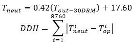
Equation (1) uses the 30-day running mean outdoor temperature (T_(out-30DRM) ) to calculate neutral temperature (T_neut ). The absolute difference between the calculated neutral temperature and the observed indoor operative temperature within the space at hour ‘i’ is the degree of discomfort for that hour. Summation of DDH across 8,760 hours yields the annual DDH. Equation (2) presents the computation of DDH.
3.1.2 Determining Comfortable Hours
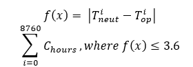
This standard defines ‘Comfortable hours’ (C_hours) as the number of hours the indoor operative temperature falls within the 80% acceptability range. 80% acceptability range is defined as deviation of 3.6℃ around the neutral temperature (T_neut).
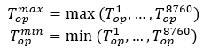
3.1.3 Maximum and minimum indoor operative temperature
Maximum and minimum indoor operative temperatures are indicative of degree of discomfort. The maximum and minimum indoor operative temperature can be found out.
3.2 Performance levels to demonstrate compliance
As outlined in performance scope, Section §3.4, this standard identifies three progressive grades of design for thermal comfort performance; Level A, Level A+ and Level A++. The first grade of performance (Level A) defines the minimum level of thermal comfort performance which is recognized as the mandatory performance criteria (Section §4.3.1) for achieving compliance. Level A+ and Level A++ are voluntary enhanced performance levels. Level A+ implies improvement in thermal comfort performance (over Level A), and Level A++ implies further improvement in performance (over Level A+).
3.2.1 Minimum level of thermal comfort performance
The standard defines a minimum level of thermal comfort performance (or Level A) for each climate zone. The defined level of performance ‘Level A’ is the indicative thermal performance achievable through the design of the envelope for desirable thermal gains/losses and ventilation performance, and improved comfort ventilation through use of ceiling fans and exhaust fans. ‘Level A’ performance in terms of comfortable hours characterized by 80% comfort limit has been outlined in Table 1.
Table 1 Percentage of hours when 80% occupants are expected to be thermally comfortable
| Cold | composite | Hot-Dry | Temperate | Warm-Humid | |
|---|---|---|---|---|---|
| Comfortable Hours (%) |
55% | 65% | 80% | % | 90% |
Note: (Considering 80% acceptability as per IMAC-R model)
3.2.2 Performance for progressive grades Level A+ and Level A++
Level A+ and Level A++ lead to improvement in thermal comfort performance over Level A through improvements in building envelope alone,
and not considering active cooling or heating equipment, with the exception of fans for circulation and exhaust. The requirements for
improvement are outlined in Sections §5.2 and 5.3. The improvement in comfort for different climates is outlined in Table 2 in terms of
improvement over
Level A in Peak Temperature Difference (in ℃), and Degree Discomfort Hours (DDH) Avoided.
This is provided as information only, and does not have to be proven while applying the standard.
Table 2 Thermal Comfort performance thresholds by climate
| Climate | Peak Temp. difference | DDH Avoided (in %) | |||
|---|---|---|---|---|---|
| Level of performance | A+ | A++ | Season | A+ | A++ |
| Cold | 1.00 | 2.50 | Winter | 10% | 25% |
| Composite | 1.00 | 1.50 | Summer | 10% | 25% |
| Hot-Dry | 0.90 | 1.20 | Summer | 8% | 15% |
| Temperate | 0.60 | Summer | 5% | ||
| Warm-Humid | 0.60 | 0.80 | Summer | 10% | 20% |
3.3 Compliance approaches
This section identifies two compliance paths for demonstrating compliance with this standard; Prescriptive and Bundle Approach. The following sub-sections outline the requirements.
3.3.1 Mandatory requirements
- This standard identifies mandatory requirements that are to be met irrespective of the chosen compliance path and/or level of performance. Sections § 5.1, 6.1, 7.1 and 8.1 outline the minimum requirements to be met for compliance with this standard.
- To demonstrate compliance with this standard, meeting at least Level A performance criteria is mandatory.
- Documentation requirements for Mandatory requirements are outlined in Section §4.4 and further outlined in Compliance Forms in Section §10.5.
- This standard proposes only low-energy systems in conjunction with solar passive design to supplement thermal comfort performance. Buildings that use mechanical space conditioning, therefore, must demonstrate Level A++ compliance with building envelope provisions in Section §5.
3.3.2 Prescriptive approach
The Prescriptive approach prescribes minimum, maximum or range of values for envelope components. This approach allows compliance with the minimum level of thermal comfort performance Level A and enhanced levels of thermal comfort performance (Level A+ and Level A++).
The following provisions must be met with:
- Mandatory requirements outlined in Section §4.3.1, as applicable, and,
- Requirements outlined in §Section 5.2. for the selected level of thermal comfort performance or higher must be demonstrated.
3.3.3 Bundle approach
The Bundle approach simplifies compliance by providing solution-sets comprising of pre-compiled envelope assemblies that may be adopted by buildings as it is. This approach allows compliance with the minimum level of thermal comfort performance (Level A) and enhanced levels of thermal comfort performance (Level A+ and Level A++).
The following provisions must be met with.
- Mandatory requirements outlined in Section §4.3.1, as applicable, and,
- Requirements outlined in §Section 5.2. for the selected level of thermal comfort performance or higher must be demonstrated.
3.4 Compliance documentation
Construction documents and specifications documenting and demonstrating compliance with various provisions of this standard will be submitted to the authority having jurisdiction for verification. The details to be submitted shall include, but are not limited to :
- Construction drawing set complete with,
- Site plan outlining building footprint, tree canopy area and hard paved areas.
- Floor plans
- Sections
- Elevations
- Material schedules along with material specifications
- Schedule of openings along with shading details
- Area statements
- Material specification sheets (from manufacturer)
- U-factor, SHGC and VLT for non-opaque assemblies
- Conductivity and density of materials utilized in opaque assemblies exposed to the external environment. Emittance and reflectance of materials of the outer-most surface in these assemblies is required as applicable.
- Calculations for,
- Window area to exposed wall area ratio (by wall surface)
- Window area to carpet area ratio
- Operable window area to carpet area ratio
- U-factor for composite opaque assemblies
- Density for composite opaque assemblies
- Equipment schedules
- Inventory of equipment (lights, ceiling fans, exhaust fans, space conditioning equipment) along with respective energy performance data.
- Conductivity and density of materials utilized in opaque assemblies exposed to the external environment. Emittance and reflectance of materials of the outer-most surface in these assemblies is required as applicable.
- Any other information outlined in compliance forms outlined
- Any other supplemental information as stipulated by the Authority Having Jurisdiction.
4. Building envelope
4.1 Mandatory requirements
This section identifies mandatory requirements for meeting a minimum level of thermal comfort performance. Sections §5.1.1 and §5.1.2 identify the requirements for testing and certifying opaque and transparent materials for thermal performance, respectively. These sections also identify alternate requirements in case testing and certification are not met with.
4.1.1 Opaque Construction
U-factor for opaque construction assemblies shall be determined in accordance with ISO-6946. Building materials must be tested in accordance with respective standards by an independent laboratory and labeled or certified by the manufacturer. For unrated products, use default tables in Appendix Section §10.2.1. Sample U-factor calculation along with example has been outlined in Appendix Section §10.2.3.
- Solar Reflectance and Thermal Emittance for exposed roof surfaces shall be determined as per standard test methods outlined in ANSI/CRRC S100 (2021). For external wall surfaces, solar reflectance and thermal emittance shall be tested as per procedures laid down in Wall Product Rating Program Manual CRRC-2. The tests must be conducted by an independent accredited laboratory and the tested products must be labeled or certified by the manufacturer or recognized certifying agency.
- Solar Reflectance Index (SRI) for exposed surface (roof or wall) shall be determined in accordance with ASTM E1980-11(2019). The tests must be conducted by an independent accredited laboratory and the tested products must be labeled or certified by the manufacturer or recognized certifying agency.
4.1.2 Fenestration
- Glazing products must be tested for, U-factor, Solar Heat Gain Coefficient (SHGC) and Visible Light Transmittance (VLT), in accordance with ISO-9050. The tests must be conducted by an independent accredited laboratory and the tested products must be labeled or certified by the manufacturer or recognized certifying agency.
- To avoid thermal bridging and limit infiltration gains/losses, framing material for fenestration shall be as
Table 3 Acceptable materials for window frames
| Climate | Unconditioned | Conditioned |
|---|---|---|
| Warm (Composite, Hot-dry, Temperate and Warm-humid) | Wood or Vinyl, or Metal with thermal break. | Wood or Vinyl |
| Cold | Wood or Vinyl | Wood or Vinyl |
4.1.3 Access and control of windows/ventilators for ventilation, daylight and views in habitable spaces
- All habitable rooms must have at-least one accessible window, ventilator or door opening directly to an exterior open space. The minimum requirements for qualifying as an exterior open space have been defined in Clause §8.2.1, §8.2.3 §8.2.6 and §8.4 Part 3 – Development Control Rules and General Building Requirements of the National Building Code of India 2016, Volume 1 as applicable.
- The openable windows for all habitable rooms must meet the requirements for minimum openable window area to floor area ratio outlined in Table 4. The openable window area includes all openings in habitable rooms that can be operated, including windows, ventilators and excluding doors. For partly fixed windows and ventilators, only the operable part will be considered for calculating minimum openable window area. Minimum openable window area calculations may be inclusive of frame. The floor area used to compute minimum openable window area to floor area ratio will be the Carpet Area of the habitable space.
- To maintain thermal comfort, the overall Window area to Floor area ratio must not exceed 45%. Further, to limit localized discomfort due to radiant asymmetry, no singular wall shall exceed window to wall ratio (including windows and ventilators) more than 25%. The floor area used to compute window area to floor area ratio will be the Carpet Area of the habitable space. The window to wall ratio for any given wall will be the ratio of glazed area inclusive of frame and the area of wall exposed to the exteriors.
- To ensure enhanced ventilation in habitable rooms, the cill level shall not exceed 0.75m. Ventilators are exempt from this requirement. For habitable rooms that include kitchen, windows meant for removal of products of combustion (emanating from chullahs, stoves, gas appliances, etc.) are also exempt from this requirement.
- All glazing used in the building should meet minimum Visible Light Transmittance (VLT) of 0.3.
Table 4 Minimum window and window opening areas expressed as floor area ratios
| Climate Type | Minimum openable window area to Floor area ratio |
|---|---|
| Hot-Dry | 1/10th of carpet area (10.0%) |
| Composite | 1/8th of carpet area (12.5%) |
| Temperate | 1/8th of carpet area (12.5%) |
| Warm-Humid | 1/6th of carpet area (16.7%) |
| Cold | 1/12th of carpet area (8.3%) |
4.1.4 Access and control of windows/ventilators for ventilation in kitchen, bath and water closets.
- Kitchen space must have at-least one accessible window or ventilator opening directly to an exterior open space. The requirements for qualifying as an exterior open have been referenced in Section §5.1.3.1.The minimum openable window area, inclusive of frame and after provision of exhaust fan, must meet the requirements outlined in Section §4.30 of Model Building Bye-laws, 2016.
- Bath and water closet must have at-least one accessible window or ventilator opening directly to an exterior open space or shaft. The requirements for ventilation shaft will be as per Section §4.30.2 of Model Building Bye-laws 2016. The requirement for window area and minimum dimensions must be as per requirements outlined in Section §4.30 of Model Building Bye-laws, 2016. At least one half of the provided window should be operable.
4.1.5 Building envelope sealing
Wherever applicable, the following shall be sealed, caulked, or weather-stripped:
- All windows, ventilators and doors shall also be weather sealed.
- Openings between wall panels, walls and roof.
- Building assemblies used as ducts or plenums.
4.1.6 Window shading
- Minimum shading requirements for windows based on climate type, orientation and location have been identified. Either of overhang (O/H) or fin or a combination of both may be used to demonstrate compliance. In case of multiple shading devices, the higher projection factor will be considered for compliance.
- For all climates except cold, the windows shall be provided with external movable shades that can be controlled and/or operated by occupants to suit their thermal comfort needs.
Table 5 Prescribed factors for shading windows based on climate, orientation and location.
| Level A | Level A+ | Level A++ | ||||
|---|---|---|---|---|---|---|
| Density (kg/m3) | <800 | >=800 | <800 | >=800 | <800 | >=800 |
| Cold | 0.80 | 0.85 | 0.60 | 0.50 | 0.35 | 0.35 |
| Composite | 0.80 | 1.00 | 0.60 | 0.80 | 0.40 | 0.45 |
| Hot-dry | 0.80 | 1.00 | 0.60 | 0.80 | 0.40 | 0.45 |
| Temperate | 0.80 | 1.00 | 0.80 | 1.00 | 0.40 | 0.45 |
| Warm-Humid | 0.80 | 1.00 | 0.60 | 0.80 | 0.40 | 0.45 |
Notes:
- ‘Either’ indicates that either of overhang (O/H) or fin may be used with indicated or better projection factors. ‘Either’ does not imply choice between ‘Left’ and ‘Right’ side fins. See note 4 for description of ‘Left’ and ‘Right’ side fins
- ‘Both’ indicates that both overhang and fin must be used with indicated or better projection factors.
- ‘-‘ indicates that the shade is optional.
- ‘L’ and ‘R’ are indicate ‘Left’ & ‘Right’ positions for fin as shading. Standing inside the building and facing the window, the fin shading the window from solar gains from the Left side are indicated as ‘L’. Similarly, the fin shading the window from solar gains from the Right side are indicated as ‘R’.
- Shading factors written within solid shaded blocks indicate that while shading is effective, it is unable to shade from solar gains throughout the year. Therefore, accommodating considerations of daylight, views and natural ventilation, a maximum projection factor of 1.0 is deemed as a practical trade-off.
4.1.7 High emittance and high reflectance roof surfaces
- For all climates except Cold, 100% of roof surfaces must have reflectance of 0.70 or greater and initial emittance of 0.75 or greater. Solar reflectance must be determined in accordance with ASTM E903-96 and emittance determined in accordance with ASTM E408-71, Alternatively, the roof surfaces must demonstrate Solar Refractive Index (SRI) of 78 or greater. SRI is calculated according to test standard ASTM E1980 for horizontal and low-sloped surfaces.
- Vegetated roofs and roof areas under building services, Solar Photovoltaic panels, Solar Hot-water panels and any other services are exempt from requirement in §5.1.7.1. For qualifying as a vegetated roof surface, the roof surface must maintain living vegetation 50mm or higher.
- In-situ roof surface preparations such as Lime wash, White china mosaic tiles (with white cement grout) are acceptable cool roof surfaces and need not be tested.
4.1.8 Reflective external wall surfaces
- For all climates except cold, 100% of the exterior wall surface area must be reflective. A wall is considered as a reflective surface if it has an initial solar reflectance of at least 0.60 and initial thermal emittance of at least 0.75. Solar reflectance must be measured in accordance with ASTM Standard E903-20, weighting solar spectral reflectance with the solar spectral irradiance for a sun-facing vertical surface specified by ASTM Standard G197-14. Thermal emittance shall be measured in accordance with ANSI/CRRC Standard S100-2021. Alternatively, the external face of exterior walls must meet SRI of 29. SRI values for horizontal and low-sloped surfaces calculated as per procedures laid out in ASTM E1980 are allowed to meet the requirement of vertical wall surfaces.
- Wall surface area under vegetation, building integrated Solar Photovoltaics, and any other services are exempt from the requirement in Section §5.1.8.1. To qualify as vegetated wall, the vegetation must be living with access to growing media and provision for irrigation.
4.2 Design prescription for building envelope
4.2.1 Thermal properties of External walls
- Thermal properties of external wall assembly
- External wall assembly must not exceed the prescribed conductance values outlined in Table 6 corresponding to respective climates, density range and level of thermal comfort performance.
Table 6 Minimum prescribed conductance (U-factor in W/m2.K) values for compliance for compliance with different levels of thermal comfort performance.
| Level A | Level A+ | Level A++ | ||||
|---|---|---|---|---|---|---|
| Density (kg/m3) | <800 | >=800 | <800 | >=800 | <800 | >=800 |
| Cold | 0.80 | 0.85 | 0.60 | 0.50 | 0.35 | 0.35 |
| Composite | 0.80 | 1.00 | 0.60 | 0.80 | 0.40 | 0.45 |
| Hot-dry | 0.80 | 1.00 | 0.60 | 0.80 | 0.40 | 0.45 |
| Temperate | 0.80 | 1.00 | 0.80 | 1.00 | 0.40 | 0.45 |
| Warm-Humid | 0.80 | 1.00 | 0.60 | 0.80 | 0.40 | 0.45 |
4.2.2 Thermal properties of roof assembly
Roof assembly must not exceed the prescribed conductance values outlined in Table 7. The values have been prescribed with respect to climate, and desired level of thermal comfort performance.
Table 7 Minimum prescribed conductance (U-factor in W/m2.K) values for compliance with different levels of thermal comfort performance.
| Performance Level | Level A | Level A+ | Level A++ |
|---|---|---|---|
| All climates | 0.75 | 0.45 | 0.25 |
4.2.3 Glazing properties
Glazing must not exceed the prescribed conductance and SHGC values outlined in Table 8. The values have been prescribed with respect to climate, and desired level of thermal comfort performance.
Table 8 Minimum prescribed conductance (U-factor in W/m2.K) and SHGC values for compliance with different levels of thermal comfort performance.
| Performance Level | Level A | Level A+ | Level A++ | |||
|---|---|---|---|---|---|---|
| Performance Metric | U-Value | SHGC | U-Value | SHGC | U-Value | SHGC |
| Cold | 3.8 | 0.7 | 2.8 | 0.7 | 1.8 | 0.6 |
| All Other Climates | 5.7 | 0.6 | 4.8 | 0.4 | 2.8 | 0.4 |
4.2.4 Window placement and configurations
For all habitable rooms, the placement and number of windows on external walls for respective thermal comfort performance shall be as per Table 9.
Table 9 Prescribed glazing configurations for different levels of thermal comfort performance.
| Performance Level | Level A | Level A+ | Level A++ |
|---|---|---|---|
| Configuration of windows | When only one external side has provision for windows, at-least 2 windows are required on this side. | Windows on at least two external walls. | Windows on at least two external walls. |
4.3 Performance bundles
The bundle approach requires choosing a bundle as per desired level of thermal comfort performance. Outline the three levels of thermal comfort performance for the 5 climate types of India. Refer the table for respective climate and adopt bundle strategy for desired level of thermal comfort performance. The bundles for each level of thermal comfort performance provide flexibility in strategy by offering a choice from light-weight, heavy weight and alternative construction practices.
Table 10 Description of assemblies by level of performance for Cold climate
| Performance Level | Bundle Description | Level A | Level A+ | Level A++ |
|---|---|---|---|---|
| External Wall | Light-weight construction Medium/ Heavy-weight construction |
AAC block-work Key Specifications AAC block work 200 mm thick Block work with internal insulation (rigid insulation board) Key Specifications 230mm Fly-ash brick with 25mm insulation (XPS or PUF) |
AAC block-work Key Specifications AAC block work 300 mm thick Block work with internal insulation (rigid insulation board) Key Specifications 230mm Fly-ash brick with 25mm insulation (XPS or PUF) |
AAC block-work with internal insulation (rigid insulation board)
Key Specifications AAC block work 150 mm thick with 50 mm insulation (PUF). Block work with internal insulation (rigid insulation board) Key Specifications 230mm Fly-ash brick with 25mm insulation (XPS or PUF) |
| Roof | Typical construction | RCC slab topped with foam concrete. Key Specifications 75mm Foam concrete over RCC slab as/design |
AAC block-work Key Specifications AAC block work 300 mm thick |
AAC block-work with internal insulation (rigid insulation board)
Key Specifications AAC block work 150 mm thick with 50 mm insulation (PUF). |
| Glazing | Provide glazing compliant with specifications corresponding to level of performance outlined | Provide glazing compliant with specifications corresponding to level of performance outlined | Provide glazing compliant with specifications corresponding to level of performance outlined | Provide glazing compliant with specifications corresponding to level of performance outlined |
| Shading | Provide appropriate shading as per Section §4.1.4 | Provide appropriate shading as per Section §4.1.4 | Provide appropriate shading as per Section §4.1.4 | Provide appropriate shading as per Section §4.1.4 |
5. Low - energy systems
5.1 Mandatory requirements
5.1.1 Provision of ceiling fan for achieving thermal comfort
5.1.1.1 Each dwelling room must be provided with one or more ceiling fan/s. The guidance on optimum room size being serviced by the number of fans for various sweep sizes are provided in Clause § 4.7.4, Part 8 Building Services - Section 1 Lighting and Natural Ventilation of the National Building Code of India 2016, Volume 2.
5.1.1.2 The installed ceiling fans must meet BEE Star Label certification or better as indicated in Table 13 for respective levels of thermal comfort performance.
Table 13 Minimum efficiency requirements for ceiling fans for respective levels of thermal comfort performance.
| Level A | Level A+ | Level A++ | |
|---|---|---|---|
| Star Rating | BEE 3 Star or better | BEE 4 Star or better | BEE 5 Star or better |
5.1.2 Provision of table/wall-mounted fan or pedestal fan
5.1.2.1 The installed table/wall-mounted fans and pedestal fans must meet BEE Star Label certification or better as indicated in Table 14 for respective levels of thermal comfort performance.
Table 14 Minimum efficiency requirements for ceiling fans for respective levels of thermal comfort performance.
| Level A | Level A+ | Level A++ | |
|---|---|---|---|
| Star Rating | BEE 3 Star or better | BEE 4 Star or better | BEE 5 Star or better |
5.1.3 Minimum ventilation in kitchen, bathroom and lavatories
5.1.3.1 Mechanical ventilation must be provided to meet minimum ventilation requirements for kitchen, bathroom and lavatories as per Section §4.3.2 Kitchen and §4.3.3 Bathrooms and Water Closets of IS:3362 – 1977 Code of practice for natural ventilation of residential buildings. For kitchen, bathroom and lavatories up to 12m2 in area, provide exhaust fan with minimum power of 25 Watts. For kitchen, bathroom and lavatories exceeding 12m2 in area provide demonstrate exhaust rate of 6 air changes per hour.
5.1.4 Design conditions for space conditioning systems
5.1.4.1 Space conditioning (cooling and heating) systems, if installed, will be designed to maintain indoor conditions for thermal comfort for the given outdoor conditions.
- Indoor design conditions: For meeting comfort requirements, the indoor conditions, as per ASHRAE Handbook – Fundamentals Chapter 17, shall be designed for 24℃ dry bulb with relative humidity in the range of 50-65% for cooling, and 20℃ dry bulb with relative humidity 30% or above for heating. The indoor design conditions shall accommodate recommended ventilation loads outlined Section 1 - Lighting and Natural Ventilation, Part 8 - Building Services, of National Building Code. Internal loads and occupancy shall be as per design.
- Outdoor design conditions: The outdoor design conditions to be considered for the design of space conditioning systems will be for normal comfort conditions as per Clause 5, Section 3 - Air-conditioning Heating and Mechanical Ventilation, Part 8 - Building Services of National Building Code. Outdoor conditions from Table 2 (of Section 3 - Air-conditioning Heating and Mechanical Ventilation, Part 8 - Building Services of National Building Code) will be used for designing cooling for 1% design dry-bulb temperature and mean coincident wet bulb temperature, and heating for 99% design dry-bulb temperature.
5.1.5 Minimum efficiency for mechanical conditioning systems
5.1.5.1 If any spaces are mechanically conditioned, the space cooling and/or heating systems must meet either of the following requirements as applicable,
- If labeled under the Star Rating program of the Bureau of Energy Efficiency (BEE),
the cooling and/or heating equipment must be BEE 5 star labeled. The following equipment are under labeling currently,
- Unitary, Split, Packaged Air Conditioners (Variable and Fixed Speed)
- Light Commercial Air Conditioners (Fixed Speed)
- Chillers
A BEE 5 star labeled space cooling and/or heating equipment introduced under the labeling scheme in the future will automatically meet compliance with this requirement.
- Any space cooling and/or heating system other than the labeled products must meet or exceed minimum efficiency requirements corresponding to Super ECBC level, as outlined in Section §5.3 of the latest amendment of ECBC 2017.
5.1.6 Ancillary components/equipment aiding mechanical space conditioning
5.1.6.1 Any ancillary components aiding space cooling and/or heating equipment, including but not limited to air-handlers, pumps, cooling towers, etc., as applicable to the design, shall meet efficiency requirements corresponding to Super ECBC level, outlined in Section §5.3 of the latest amendment of ECBC 2017.
5.1.7 Low-energy comfort systems for space conditioning
5.1.7.1 In case low-energy comfort systems are installed in the project, these systems shall meet or exceed Super ECBC requirements outlined in Section §5.3.13 of the latest amendment of ECBC 2017. Section §5.3.13 of the latest amendment of ECBC 2017 identifies approved alternative HVAC systems, Super ECBC requirements and documentation requirements.
5.1.8 Piping and duct-work
Piping and duct-work for heating, space conditioning and service water heating shall meet the following insulation requirements.
5.1.8.1 Piping Insulation. Refer Section §5.2.4.1 - Piping Insulation, of the latest amendment of ECBC 2017 for minimum insulation requirements outlined for Super ECBC level.
5.1.8.2 Duct-work and plenum insulation. Refer Section §5.2.4.2 - Ductwork and Plenum Insulation, of the latest amendment of ECBC 2017 for minimum insulation requirements outlined for Super ECBC level.
6 Lighting provisions
6.1 Mandatory requirements
6.1.1 Electric Lighting requirements
Electric lighting must be designed to meet the illumination levels outlined in Table 15. The illumination levels have been referenced from the Part 8 Section 1 of NBC Volume 2 (2016).
Table 15 Illumination levels required for different space types.
| Area Description | Lux Level |
|---|---|
| Circulation Areas (Lifts, Corridors, Passageways, Stairs) | 100 |
| Bathroom/Lavatory | 150 |
| Kitchen | 500 |
| General lighting | 100 |
6.1.2 Glare from electric lighting
6.1.2.1 Lamps that are installed in the view of the occupant must be shielded to prevent disability glare. Install only shielded fixtures. For general illumination, up-lights and wall-wash lights are recommended.
6.1.3 Colour rendering ability of lamps and light fixtures
6.1.3.1 All lamps and light fixtures must meet the Colour rendering Index (CRI) requirements corresponding to the level of performance outlined in Table 16. Decorative fixtures are exempt from these requirements.
Table 16 Colour rendering requirements for lamps and light fixtures for Level A, A+ and A++ performance.
| Level A | Level A+ | Level A++ | |
|---|---|---|---|
| Color Rendering Index | <=70 | <=80 | <=90 |
7 Other special requirements for large residential complexe
For the purpose of requirements outlined in this section, large residential complexes refers to multi-family housing spread over 1 hectare.
7.1 Mandatory requirements
7.1.1 Minimum tree canopy cover for new developments
7.1.1.1 A minimum tree canopy cover of 15% of gross site area shall be provided. Tree canopy shall include trees that are evergreen/native species and six feet or greater in height.
7.1.2 Reflective paving and road surfaces
7.1.2.1 For all climates except Cold, more than 50% of hard paved exterior surfaces visible to sky (excluding landscape area) must have high reflectance and emittance. For demonstrating compliance, all hard surfaces must demonstrate SRI of 50 or greater. SRI is calculated according to test standard ASTM E1980 for horizontal and low-sloped surfaces.
8 Definitions, abbreviations, and acronyms
A
Apartment Houses: These shall include any building or structure in which living quarters are provided for three or more families, living independently of each other and with independent cooking facilities. (National Building Code of India, Vol 1, 2016)
Authority Having Jurisdiction: The authority which has been created by a statute and which, for the purpose of administering the Code/Part, may authorize a committee or an official or an agency to act on its behalf (National Building Code of India, Vol 1, 2016).
Absorptivity (a) It is a factor indicating the relative amount of radiation absorbed by a surface as compared to an absorbing black body under the same conditions. Its value is dependent upon the temperature of the source as also that of receiving surface (SP 41 (1987): Handbook on Functional Requirements of Buildings (Other than Industrial Buildings), 1987).
Adaptive Model A model that relates indoor design temperatures or acceptable temperature ranges to outdoor meteorological or climatological parameters (ASHRAE Standard 55, 2017).
Air Change Per Hour (ACH) The amount of air leakage into or out of a building or room in terms of the number of building volumes or room volumes exchanged (SP 41 (1987): Handbook on Functional Requirements of Buildings (Other than Industrial Buildings), 1987).
B
Building Fabric: It refers to a component of any building, consisting of its roofs, walls, windows, doors etc., but excluding any mechanical system, for controlling the flow of energy between the interior and exterior of the building (Hong Kong Buildings Department, 2014).
C
Carpet Area: The net usable floor area of an apartment, excluding the area covered by the external walls, areas under services shafts, exclusive balcony or verandah area and exclusive open terrace area, but includes the area covered by the internal partition walls of the apartment (MOHUA, 2021).
Comfort Ventilation: The ventilation necessary only during certain weather conditions for the purpose of improving thermal comfort (SP 41 (1987): Handbook on Functional Requirements of Buildings (Other than Industrial Buildings), 1987).
D
Design conditions: Specified indoor environmental conditions, such as temperature, humidity and light intensity, required to be produced and maintained by a system and under which the system must operate.
Dormitory: These shall include any building in which group sleeping accommodation is provided, with or without dining facilities for persons who are not members of the same family, in one room or a series of closely associated rooms under joint occupancy and single management, for example, school and college dormitories, students, and other hostels and military barracks. (National Building Code of India, Vol 1, 2016)
Dry-bulb Temperature: The temperature of the air, read on a thermometer, taken in such a way as to avoid errors due to radiation (SP 41 (1987): Handbook on Functional Requirements of Buildings (Other than Industrial Buildings), 1987).
E
Emissivity: It is the ratio of the heat emitted by a surface as compared to that of an absolutely black surface under similar conditions. It varies with the temperature of the emitting surfaces (SP 41 (1987): Handbook on Functional Requirements of Buildings (Other than Industrial Buildings), 1987).
External movable shades: These are opaque building elements that are permanently mounted on the outside of the building and shade the windows from direct sun. They have movable elements and can be adjusted by building occupants to meet their needs for ventilation, and/or daylight. These may be controlled via manual operation or automated. Shutters, louvers, external blinds, etc. are some types of external movable shades.
F
Fenestration: Fenestration means any glazed aperture in the building envelope (Hong Kong Buildings Department, 2014). Any opening or arrangement of openings (normally filled with media for control) for the admission of daylight (SP 41 (1987): Handbook on Functional Requirements of Buildings (Other than Industrial Buildings), 1987).
G
Glare: It is the effect of brightness or brightness differences within the visual field which causes annoyance, discomfort or loss of visual performance (SP 41 (1987): Handbook on Functional Requirements of Buildings (Other than Industrial Buildings), 1987).
Glazing: Often used interchangeably with window or glass. The term refers specifically to just the clear material which admits sunlight. And so can also be plastic. Double and triple glazing refer to two or three panes (Passive Solar Design Strategies: Guidelines for Home Building, 2009).
H
Habitable Room: A room occupied or designed for occupancy by one or more persons for study, living, sleeping, eating, kitchen if it is used as a living room, but not including bathrooms, water-closet compartments, laundries, serving and store pantries, corridors, cellars, attics, and spaces that are not used frequently or during extended periods (Model Building Bye-laws, 2016).
L
Low-emissivity: The term refers to a surface's ability to absorb and re-radiate heat. A material with a low emissivity absorbs and re-radiates relatively small amounts of heat. Low-emissivity or "low-e" glass sandwiches a thin layer of metallic film or coating between two panes of glass. The low-e glass blocks radiant heat, so it will tend to keep heat energy inside the house during the winter. And keep heat energy outside the house during the summer (Passive Solar Design Strategies: Guidelines for Home Building, 2009).
M
Mechanical Cooling: Cooling of the indoor environment by mechanical means used to provide cooling of supply air, fan coil units, cooled surfaces etc. (Dodd et al., 2020).
N
Natural Ventilation: Supply of outside air into a building through window or other openings due to wind outside and convection effects arising from temperature or vapour pressure differences (or both) between inside and outside of the building (SP 41 (1987): Handbook on Functional Requirements of Buildings (Other than Industrial Buildings), 1987).
O
One- or two-family private dwellings: These shall include any private dwelling, which is occupied by members of one or two families and has a total sleeping accommodation for not more than 20 persons (National Building Code of India, Vol 1, 2016).
Operative/Resultant Temperature: The average of the mean radiant temperature and the air temperature. This measurement is the best indication of the temperature perceived by an occupant (Mikler et al., 2009)
The uniform temperature of an imaginary black enclosure, and the air within it, in which an occupant would exchange the same amount of heat by radiation plus convection as in the actual nonuniform environment; calculated in accordance with Normative Appendix A of ASHRAE 55 standard (ASHRAE Standard 55, 2017).
P
Passive Solar: Whole building design and construction techniques which help a building make use of solar energy by non-mechanical means. As opposed to active solar techniques which use equipment such as roof-top collectors (Passive Solar Design Strategies: Guidelines for Home Building, 2009)
Prevailing mean outdoor temperature: When used as an input variable the adaptive model, this temperature is based on the arithmetic average of the mean daily outdoor temperatures over defined period (say 7 days) (ASHRAE Standard 55, 2017).
S
Shading Coefficient: It is the measure of how much solar heat will be transmitted by a glazing material. as compared to a single pane of clear uncoated glass. which has a shading coefficient (SC) of 1. For example. clear double-pane glass might have an SC in the range of .88. Reflective glass might have SC's of .03 - .06. In general. lower shading coefficients are desirable when heat gain is a problem (Passive Solar Design Strategies: Guidelines for Home Building, 2009).
Shade Factor: It is defined as,
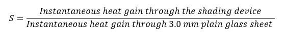
Shade factor is expressed in percent
It takes into account the heat gain through glazing, both by direct transmission and air-to-air transfer (SP 41 (1987): Handbook on Functional Requirements of Buildings (Other than Industrial Buildings), 1987)
Surface Coefficient (f): It is the quantity of heat transmitted by convection, conduction and radiation from unit area of the surface when unit difference of temperature is maintained between the surface and the surrounding medium. Its value depends upon many factors, such as orientation or position of the surface, emissivity of the surface, temperature difference and air velocity. It is expressed in W / m2 K (SP 41 (1987): Handbook on Functional Requirements of Buildings (Other than Industrial Buildings), 1987).
Surface Resistance (1/f): It is the reciprocal of surface coefficient. It is expressed in m2 K / W (SP 41 (1987): Handbook on Functional Requirements of Buildings (Other than Industrial Buildings), 1987).
T
Thermal Comfort: That condition of mind that expresses satisfaction with the thermal environment and is assessed by subjective evaluation (ASHRAE Standard 55, 2017).
Thermal Conductance (U-value): Thermal conductance per unit area is the thermal transmission of a single layer structure per unit area divided by the temperature difference between the hot and cold faces. It is expressed in W / m2 K (SP 41 (1987): Handbook on Functional Requirements of Buildings (Other than Industrial Buildings), 1987).
Thermal Capacity (q_St): It is the amount of heat that will be absorbed by the material before the ‘steady state’ condition is reached. It is the product of the mass of the material and specific heat.
where m and c are the mass and specific heat of the material (SP 41 (1987): Handbook on Functional Requirements of Buildings (Other than Industrial Buildings), 1987).
Thermal Conductivity (k): This is the quantity of heat in the ‘steady state’ conditions flowing the unit time through a unit area of a slab of uniform material of infinite extent and of unit thickness, when unit difference of temperature is established between its faces. Its unit is W / m K.
The thermal conductivity is a characteristic property of a material and its value may vary with a number of factors including density, porosity, moisture content, fibre diameter, pore size, type of gas in the material, mean temperature and outside temperature range (SP 41 (1987): Handbook on Functional Requirements of Buildings (Other than Industrial Buildings), 1987).
Thermal Mass: Material that stores energy. although mass will also retain coolness. The thermal storage capacity of a material is a measure of the material's ability to absorb and store heat. Thermal mass in passive solar buildings is usually dense material such as brick or concrete masonry, but can also be tile, water, phase change materials, etc. (Passive Solar Design Strategies: Guidelines for Home Building, 2009).
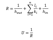
Thermal Resistance: It is reciprocal of thermal conductance. For a structure having plane parallel faces, thermal resistance is equal to thickness (L) divided by thermal conductivity (K) as given below:

The unit of thermal resistance is W / m2 K. The usefulness of this quantity is that when heat passes in succession through two or more components of the building unit, the resistance may be added together to get the total resistance of the structure (SP 41 (1987): Handbook on Functional Requirements of Buildings (Other than Industrial Buildings), 1987).
Thermal Resistivity: It is the reciprocal of thermal conductivity. It is expressed in m K / W (SP 41 (1987): Handbook on Functional Requirements of Buildings (Other than Industrial Buildings), 1987).
Thermal Transmittance: It is the thermal transmission through unit area of the given building unit divided by the temperature difference between the air or other fluid on either side of the building unit in ‘steady state’ conditions. It is reciprocal of total thermal resistance. Its unit is W/m2K.
Thermal transmittance differs from ‘Thermal conductance’ in so far as temperatures are measured on the two surfaces of material or structure in the latter case and in the surrounding air or other fluid in the former. The conductance is a characteristic of the structure whereas the transmittance depends on conductance and surface coefficients of the structure under the conditions of use (SP 41 (1987): Handbook on Functional Requirements of Buildings (Other than Industrial Buildings), 1987).
V
Ventilation: Ventilation-Supply of outside air to the interior for air motion and replacement of vitiated air (SP 41 (1987): Handbook on Functional Requirements of Buildings (Other than Industrial Buildings), 1987).
W
Window to wall ratio: The ratio of glazed areas to gross wall areas of building envelope of all enclosed spaces of residential units, except for bathrooms and enclosed kitchens (Hong Kong Buildings Department, 2014)
9 Appendices
9.1 Climate Zone map of India and list of major cities mapped to their climate zone.
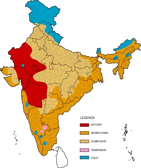
Figure 1 Climate zone map of India. Source: NBC
Table 17 List of major Indian cities mapped to their respective climate zones
| City | Climate Type | City | Climate Type |
|---|---|---|---|
| Ahmedabad | Hot & Dry | Kurnool | Warm & Humid |
| Allahabad | Composite | Leh | Cold |
| Amritsar | Composite | Lucknow | Composite |
| Aurangabad | Hot & Dry | Ludhiana | Composite |
| Bangalore | Temperate | Chennai | Warm & Humid |
| Barmer | Hot & Dry | Manali | Cold |
| Belgaum | Warm & Humid | Mangalore | Warm & Humid |
| Bhagalpur | Warm & Humid | Mumbai | Warm & Humid |
| Bhopal | Composite | Nagpur | Composite |
| Bhubaneshwar | Warm & Humid | Nellore | Warm & Humid |
| Bikaner | Hot & Dry | New Delhi | Composite |
| Chandigarh | Composite | Panjim | Warm & Humid |
| Chitradurga | Warm & Humid | Patna | Composite |
| Dehradun | Composite | Pune | Warm & Humid |
| Dibrugarh | Warm & Humid | Raipur | Composite |
| Guwhati | Warm & Humid | Rajkot | Composite |
| Gorakhpur | Composite | Ramgundam | Warm & Humid |
| Gwalior | Composite | Ranchi | Composite |
| Hisar | Composite | Ratnagiri | Warm & Humid |
| Hyderabad | Composite | Raxaul | Warm & Humid |
| Imphal | Warm & Humid | Saharanpur | Composite |
| Imphal | Composite | Shilong | Cold |
| Jabalpur | Composite | Sholapur | Hot & Dry |
| Jagdelpur | Warm & Humid | Srinagar | Cold |
| Jaipur | Composite | Sundernagar | Cold |
| Jaisalmer | Hot & Dry | Surat | Hot & Dry |
| Jalandhar | Composite | Tezpur | Warm & Humid |
| Jamnagar | Warm & Humid | Tiruchirappalli | Warm & Humid |
| Jodhpur | Hot & Dry | Trivandrum | Warm & Humid |
| Jorhat | Warm & Humid | Tuticorin | Warm & Humid |
| Kochi | Warm & Humid | Udhagamandalam | Cold |
| Kolkata | Warm & Humid | Vadodara | Hot & Dry |
| Kota | Hot & Dry | Veraval | Warm & Humid |
| Kullu | Cold | Vishakhapatnam | Warm & Humid |
9.2 Default values for typical construction
9.2.1 Opaque assemblies
Table 18 Default thermal specifications for a list of typical materials
| Material | Conductivity (W/mK) | Sp Heat (J/kgK) | Density (kg/m3) | Source |
|---|---|---|---|---|
| Solid burnt clay brick | 0.98 | 800 | 1920 | (1) |
| AC sheet | 0.245 | 1520 | (2) | |
| Aerated autoclaved concrete (AAC) block | 0.184 | 1240 | 642 | (2) |
| Brick tile | 0.798 | 880 | 1892 | (2) |
| Cellular concrete | 0.188 | 1050 | 704 | (2) |
| Cement mortar | 0.719 | 200 | 1648 | (2) |
| Cement plaster | 0.721 | 840 | 1762 | (2) |
| Cement stabilized soil block (CSEB) - High density | 1.303 | 1030 | 1900 | (2) |
| Cement stabilized soil block (CSEB) - Low density | 1.026 | 1070 | 1700 | (2) |
| Cement stabilized soil block (CSEB) - Med density | 1.201 | 1070 | 1800 | (2) |
| Dense Concrete | 1.74 | 880 | 2410 | (2) |
| Fired Clay Brick (Hi Den) | 1.119 | 955.2 | 2028 | (3) |
| Fired Clay Brick (Low Den) | 0.3757 | 927.8 | 1264 | (3) |
| Fly ash brick | 0.856 | 920 | 1650 | (2) |
| Gl sheet | 61.06 | 840 | 7520 | (2) |
| Glass | 0.814 | 960 | 2350 | (2) |
| Gypsum plaster | 0.512 | 1050 | 1120 | (2) |
| Lime concrete | 0.73 | 1760 | 1646 | (2) |
| Mud phuska | 0.519 | 880 | 1622 | (2) |
| NA | ||||
| Plywood | 0.174 | 1340 | 640 | (2) |
| Reinforced cement concrete (RCC) | 1.58 | 750 | 2288 | (2) |
| Resource efficient (hollow) brick | 0.631 | 750 | 1520 | (2) |
| Solid concrete block 25/50 | 1.396 | 920 | 2427 | (2) |
| Solid concrete block 30/60 | 1.411 | 920 | 2349 | (2) |
| Timber | 0.072 | 960 | 2349 | (2) |
| Timber | 0.144 | 160 | 2249 | (2) |
| Extruded Polystyrene (XPS) | 0.028 | 1213 | 35 | (1) |
| Expanded Polystyrene (EPS) | 0.028 | 1213 | 35 | (1) |
| Sandstone | 1.83 | 840 | 2420 |
9.2.2 Convective heat transfer coefficient of air film
The air-film along the wall and roof on bot interior and exterior surfaces has an impact on the overall thermal conductance of the construction assembly. Default values of convective heat transfer coefficient of air film are compiled in Table 19. Please refer Section §10.2.3 on how to use these values for calculating overall U-factor.
Table 19 Default values of convective heat transfer coefficient of air film (Adapted from Energy Conservation Building Code User Guide (BEE, 2009))
| Wall | Roof | ||
|---|---|---|---|
| All climate zones | Composite, Hot-dry, Warm-humid and Temperate climate | Cold climate | |
| 1⁄h_out | 0.04 | 0.04 | 0.04 |
| 1⁄h_in | 0.13 | 0.17 | 0.10 |
9.2.3 Calculating U-factor
For a typical opaque construction assembly, i.e. wall or roof, typical construction assembly will be compiled layer by layer and the following equation will be applied for calculating overall U-factor of the compiled assembly. Layer by layer material specifications may be compiled from the list of materials in Table 18.

Figure 2 A schematic section of multi-layer opaque construction assembly
| Layer # | Thickness | Conductivity | Resistance |
|---|---|---|---|
| Layer 1 | l_1 | k_1 | l_1⁄k_1 |
| Layer 2 | l_2 | k_2 | l_1⁄k_1 |
| --- | |||
| Layer n | l_n | k_n | |
| Layer 2 | l_2 | k_2 | l_n⁄k_n |
A list of typical wall and roof assemblies along with their default characteristics has been compiled here for ready reference in Table 20 and Table 21.
9.3 Roof assembly bundles
9.3.1 Insulated (under-deck) slab
Surface type: External, Flat-roof slab
Layer order: Outside to inside
- Finishing surface (tiles, stone, etc.) applied over cement mortar
- Plain Cement Concrete (PCC) screed laid to slope
- Water proofing layer
- Reinforced Cement Concrete (RCC) slab (as/structural design) thoroughly cleaned of all dust, dirt and loose particles with wire brush
- Rigid insulation board applied with adhesive, held in place with screws and joints sealed with tape.
Key material specifications:
| Item | Specifications | |
|---|---|---|
| Rigid insulation | Type | Extruded polystyrene (XPS) |
| Density | 34-36 kg/m3 | |
| Conductivity | 0.029 W/mK | |
| Thickness | Refer ‘Key Specifications’, as applicable, outlined in Table 10, Table 11 and Table 12. | |
| Interior paint finish | Description | Light coloured paint |
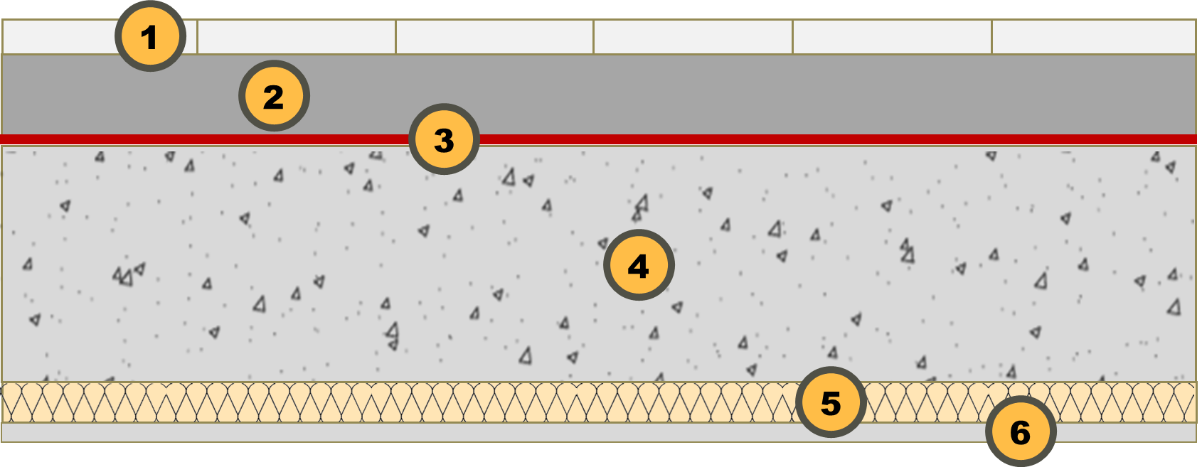
Figure 3 Construction detail for insulated (rigid insulation board – extruded polystyrene) slab - under deck
9.3.2 RCC slab with foam concrete and under-deck insulation
Surface type: External, Flat-roof slab
Layer order: Outside to inside
- Finishing surface (tiles, stone, etc.) applied over cement mortar
- Plain Cement Concrete (PCC) screed laid to slope
- Water proofing layer
- Reinforced Cement Concrete (RCC) slab (as/structural design) thoroughly cleaned of all dust, dirt and loose particles with wire brush
- Rigid insulation board applied with adhesive, held in place with screws and joints sealed with tape.
Key material specifications:
| Item | Specifications | |
|---|---|---|
| Rigid insulation | Type | Extruded polystyrene (XPS) |
| Density | 34-36 kg/m3 | |
| Conductivity | 0.007 W/mK | |
| Thickness | Refer ‘Key Specifications’, as applicable, outlined in Table 10, Table 11 and Table 12. | |
| Interior paint finish | Description | Light coloured paint |
Figure 4 Construction detail for roof assembly: RCC slab with foam concrete insulation
9.3.3 Insulated (rigid insulation board - extruded polystyrene or polyurethane foam) slab - over deck
Surface type: External, Flat-roof slab
Layer order: Outside to inside
- Broken china mosaic (white tiles grouted with white cement) applied on cement mortar
- Water proofing layer
- Cement screed with welded mesh
- Polythene sheet/Geo-textile membrane
- Rigid insulation board applied with water-based adhesive
- Brick-batts/Plain Cement Concrete (PCC) laid to slope
- Reinforced Cement Concrete (RCC) slab (as/structural design)
Key material specifications:
| Item | Specifications | |
|---|---|---|
| Rigid insulation | Type | Extruded polystyrene (XPS) |
| Density | 34-36 kg/m3 | |
| Conductivity | 0.007 W/mK | |
| Thickness | Refer ‘Key Specifications’, as applicable, outlined in Table 10, Table 11 and Table 12. | |
| Interior paint finish | Description | Light coloured paint |
Figure 5 Construction detail for insulated (rigid insulation board – extruded polystyrene) slab - over deck
9.4 Wall assembly bundles
9.4.1 AAC block-work
Surface type: External, wall assembly
Layer order: Outside to inside.
- Exterior paint
- External cement plaster (GI chicken wire mesh over block-work and structure joints)
- AAC block work
- Internal cement plaster
- Interior paint
Key material specifications:
| Item | Specifications | |
|---|---|---|
| AAC block work | Type | Autoclave Aerated Concrete Block (AAC) |
| Density | Less than 700 kg/m3 | |
| Conductivity | 0.0018 W/mK | |
| Thickness | Refer ‘Key Specifications’, as applicable, outlined in Table 10, Table 11 and Table 12. | |
| Exterior paint finish | Description | Light coloured paint |
| Interior paint finish | Description | Light coloured paint |

Figure 7 Construction detail for wall assembly: AAC block
9.4.2 AAC block-work with internal insulation
Surface type: External, wall assembly with internal insulation
Layer order: Outside to inside
- Exterior finish (as/design)
- External cement plaster (GI chicken wire mesh over block-work and structure joints)
- AAC block work
- Internal cement plaster
- Interior paint
Key material specifications:
| Item | Specifications | |
|---|---|---|
| AAC block work | Type | Autoclave Aerated Concrete Block (AAC) |
| Density | Less than 700 kg/m3 | |
| Conductivity | 0.0018 W/mK | |
| Thickness | Refer ‘Key Specifications’, as applicable, outlined in Table 10, Table 11 and Table 12. | |
| Exterior paint finish | Description | Light coloured paint |
| Interior paint finish | Description | Light coloured paint |
Figure 8 Construction detail for wall assembly: AAC block with rigid board insulation on the inside
9.4.3 AAC block-work with external insulation
Surface type: External, wall assembly with external insulation
Layer order: Outside to inside
- Exterior finish (as/design)
- External cement plaster (GI chicken wire mesh over block-work and structure joints)
- AAC block work
- Internal cement plaster
- Interior paint
Key material specifications:
| Item | Specifications | |
|---|---|---|
| AAC block work | Type | Autoclave Aerated Concrete Block (AAC) |
| Density | Less than 700 kg/m3 | |
| Conductivity | 0.0018 W/mK | |
| Thickness | Refer ‘Key Specifications’, as applicable, outlined in Table 10, Table 11 and Table 12. | |
| Exterior paint finish | Description | Light coloured paint |
| Interior paint finish | Description | Light coloured paint |
Figure 9 Construction detail for wall assembly: AAC block with external insulation
9.4.4 Fly-ash block-work with internal insulation
Surface type: External, wall assembly with external insulation
Layer order: Outside to inside
- Exterior finish (as/design)
- External cement plaster (GI chicken wire mesh over block-work and structure joints)
- AAC block work
- Internal cement plaster
- Interior paint
Key material specifications:
| Item | Specifications | |
|---|---|---|
| AAC block work | Type | Autoclave Aerated Concrete Block (AAC) |
| Density | Less than 700 kg/m3 | |
| Conductivity | 0.0018 W/mK | |
| Thickness | Refer ‘Key Specifications’, as applicable, outlined in Table 10, Table 11 and Table 12. | |
| Exterior paint finish | Description | Light coloured paint |
| Interior paint finish | Description | Light coloured paint |
Figure 10 Construction detail for wall assembly: Fly-ash block with internal insulation
9.4.5 Fly-ash block-work with internal insulation
Surface type: External, wall assembly with external insulation
Layer order: Outside to inside
- Exterior finish (as/design)
- External cement plaster (GI chicken wire mesh over block-work and structure joints)
- AAC block work
- Internal cement plaster
- Interior paint
Key material specifications:
| Item | Specifications | |
|---|---|---|
| Rigid insulation | Type | Extruded Poly-styrene (XPS) or Polyurethane Foam (PUF) |
| Density | 34-36 kg/m3 (XPS) or 38-42 kg/m3 (PUF) | |
| Conductivity | 0.029 W/mK (XPS) or 0.026 W/mK (PUF) | |
| Thickness | Refer ‘Key Specifications’, as applicable, outlined in Table 10, Table 11 and Table 12. | |
| Exterior paint finish | Description | Light coloured paint |
| Interior paint finish | Description | Light coloured paint |
Figure 11 Construction detail for wall assembly: Fly-ash block with external insulation