
A What is thermal comfort? Fundamentals

ISO 7730 defines thermal comfort as '…that condition of mind which expresses satisfaction with the thermal environment.'

Thermal Comfort is influenced by Personal and Environmental factors.
The personal factors are determined by occupant behaviour, i.e,
- the kind of activity that is being performed - running, sitting, walking, cooking, etc., and,
- the type of clothing – thick and insulating (like woolens) or light and breathable (say light cotton fabric)
The environmental factors on the other hand represent the ‘behaviour’ of the occupants’ environment i.e.,
- the moisture holding capacity of the air,
- the air temperature,
- the temperature of objects surrounding the occupant (expressed as mean radiant temperature)
- the velocity of air that the occupant is in contact with.
While both factors are critical to achieving thermal comfort, it is the indoor environmental factors that can be controlled by the designer through passive design. Prudence in building orientation, design of form and building envelope, and choice of materials impact Thermal Comfort
B Physiological response to discomfort Fundamentals
The human body maintains its core temperature between 36.5 and 37.5 °C (or 97.7 and 99.5 °F). This thermo-regulatory mechanism comes under stress in extreme conditions.
When the body is exposed to hot environment, the human thermoregulatory system tries to cool down the body through two mechanisms – ‘vasodilation’ and ‘sweating’. Under vasodilation, the blood vessels expand to increase blood flow near the skin, in turn increasing the rate at which the body can expel heat. Sweating is an evaporative cooling mechanism employed by the body. The cooling sensation felt on the skin when sweat evaporates is because sweat absorbs body heat to evaporate.
Similarly, the human body employs mechanisms for keeping warm when the body is exposed to cold environment. To keep warm, the blood vessels narrow (or vasoconstrict) to reduce blood flow to the skin. This means internally generated heat not lost to the skin as readily. In addition to vasoconstriction, the human body produces involuntary movement in skeletal muscles, also known as shivering to stay warm.

C Adaptive thermal comfort Fundamentals
Thermal comfort is fraught with subjectivity and has been widely researched over the last few decades. In terms of understanding thermal comfort, one approach has been to observe physiological response and thermal perception of people in controlled environment. Fanger Comfort Model, Pierce Two-node Model, and KSU Two-node Model are examples of this approach.
Another approach, that deviates from the first approach, recognizes the ability of the human body to adapt, albeit within limits, to existing conditions based on past thermal experience and contextual factors. This approach moves away from tightly controlled mechanically conditioned buildings that operate in narrow comfort bands, to naturally ventilated or mixed-mode buildings that operate on broader and flexible comfort bands. Although suited to unconditioned buildings, this approach does not preclude mechanical conditioning solutions. This approach uses statistical analyses of thermal comfort response obtained from diverse building occupants spread over time (seasons) and space (geography), and complemented with measurement of key environmental parameters (at the time of survey).


D Measuring thermal comfort Fundamentals
Index - Indoor Operative Temperature
There are more than 40 indices to measure thermal comfort (indoor and outdoor). The Indoor Operative Temperature is one of the simpler metrics that is also utilised by the adaptive comfort model for determining acceptable temperature ranges.
For better understanding, it is important to distinguish operative temperature from air temperature. For example, you may be in a space with seemingly comfortable temperature, but a nearby radiative source may be causing you thermal discomfort. The indoor operative temperature accounts for the radiative component (along with air temperature) and air velocity to a degree, to better approximate thermal expectations. It is because of this, operative temperature can serve better for control of building systems (say window, ceiling fan or mechanical systems operation).
The Indoor operative temperature takes into account; the air temperature, mean radiant temperature and air speed. At air velocities less than 0.2 m/sec (or 40 feet per minute), the operative temperature is the mean of dry bulb temperature and mean radiant temperature


Metric – Degree Discomfort Hour (DDH)
Indoor operative temperature also presents an opportunity to measure discomfort severity. Discomfort severity is measured in terms of ‘Degree Hours’, i.e. the deviation from desired temperature at a given hour. For example, if the desired (or neutral) temperature at a given hour is 25°C and the operative temperature is 34°C, then the operative temperature exceeds thermal expectations for that hour by 9 degree-hours. Cumulating discomfort for each hour annually provides an annualized metric for discomfort.
Summer discomfort (due to overheating) is typically reported as a positive quantity, and winter discomfort is reported as a negative quantity. Therefore, cumulating Discomfort Degree Hours over seasons lends itself as a seasonal metric as well. However, for reporting annual discomfort, only absolute values of degree discomfort must be computed.

Note: Neutral temperature represents a state when occupants’ thermal vote is neutral, i.e., neither feeling hot nor cold, or in other words, feeling comfortable.
A Some of the major cities in composite climate Climate Characteristics

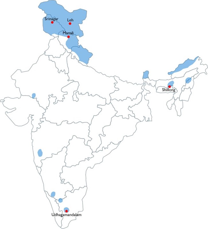
A Some of the major cities in cold climate Climate Characteristics
A Some of the major cities in Hot-dry climate Climate Characteristics

A Some of the major cities in Warm-humid climate Climate Characteristics

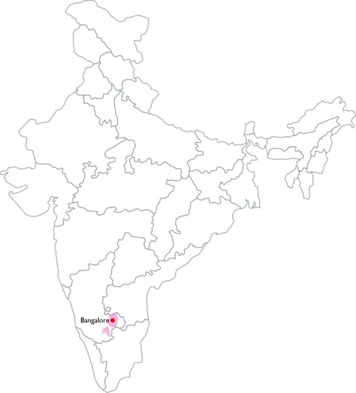
A Some of the major cities in Temperate climate Climate Characteristics
B Seasonal characteristics Climate Characteristics
 0
0oC
0
0oC
Day-time mean-max temperature range
 0
0oC
0
0oC
Night-time mean min temperature range
 0
0oC
0
0oC
Day-time mean-max temperature range
 0
0oC
0
0oC
Night-time mean min
 0
0oC
0
0oC
Temperature range
 0
0oC
0
0oC
Night-time mean min
Composite climate is characterised by three seasons; hot and dry summers, harsh winters and warm-humid monsoons. Daily extremes in summers and winters i.e., hot days and coo nights in summers and warm days and cold nights in winters are a characteristic feature of Composite climate.
B Seasonal characteristics Climate Characteristics
0
0oC
Day-time mean-max temperature range
0
0oC
Night-time mean min temperature range
0
0oC
Day-time mean-max temperature range
0
0oC
Night-time mean min
Note: Statistics compiled from Srinagar’s climate. Assumed Oct – Mar as winter period, and May – Aug summer period.
Cold climate is characterised by harsh winters and mild summers. The diurnal variation in temperatures can exceed 20°C implying that cold discomfort can occur even in warm season.
B Seasonal characteristics Climate Characteristics
0
0oC
Day-time mean-max temperature range
0
0oC
Night-time mean min temperature range
0
0oC
Day-time mean-max temperature range
0
0oC
Night-time mean min
0
0%
Humidity range
 0
0mm
0
0mm
Annual Precipitation
Hot-dry climate is characterised by two seasons; hot and dry summers, and somewhat cooler winters. Daily extremes in summers and winters i.e., hot days and cool nights in summers and warm days in winters are a characteristic feature of Hot-dry climate.
B Seasonal characteristics Climate Characteristics
0
0oC
Day-time mean-max temperature range
0
0oC
Night-time mean min temperature range
0
0oC
Typical humidity range
Warm-humid climate is characterised hot, sticky conditions nearly throughout the year. The narrow diurnal and annual range also point to vey little seasonal variation throughout the year. Sky conditions are typically cloudy throughout the year. This implies diffused solar radiation and limited potential of night-sky cooling. While radiation is diffused, it is still harsh, and combined with high humidity it is a significant cause for discomfort.

High humidity is known to affect durability of materials. Mold and algal growth, rotting of organic materials, and rusting/oxidation of metallic materials are typical concerns. Because of constant humidity and high vapour pressure, vapour diffusion through the envelope can lead to degradation of materials. This can impact health of building occupants. Careful choice of materials and incorporating judiciously placed vapour barrier are important design considerations.
Insects also thrive in these climates and this can deter occupants from using windows for ventilation. Insect screens can be integrated with windows to ensure use of windows for ventilation.
It is important to keep these considerations in mind while designing for thermal comfort and overall well being.
B Seasonal characteristics Climate Characteristics
0
0oC
Day-time mean-max temperature range
0
0oC
Night-time mean min temperature range
0
0oC
Day-time mean-max temperature range
0
0oC
Night-time mean min
0
0oC
Temperature range
0
0oC
Night-time mean min
Note: Statistics compiled from Bengaluru’s climate. Assumed Dec – Mar as winter period, Apr – Jul summer period and Jul – Oct as monsoon period.
Temperate climate is characterized by warm summers and cool winters. The temperatures are moderate throughout the year.
C Thermal comfort potential Climate Characteristics

80% acceptability criterion defined by the adaptive comfort model indicates that the comfort band (inclusive of adaptations such as clothing, ceiling fan operation, etc.) lies between 19 and 35°C dry-bulb temperature.
Note: Comfort assessments are an outcome of the application of an adaptive comfort model derived from scientific studies in the Indian residential context.

The composite climate can provide comfortable conditions for about 25% hours in a year. In terms of severity, interventions in the built environment are required for hot-dry, hot, cold and cold-humid conditions.
Note: Comfort assessments are an outcome of the application of an adaptive comfort model derived from scientific studies in the Indian residential context
C Thermal comfort potential Climate Characteristics

80% acceptability criterion defined by the adaptive comfort model indicates that the comfort band (inclusive of adaptations such as clothing, ceiling fan operation, etc.) lies between 16 and 32°C dry-bulb temperature.
Note: Comfort assessments are an outcome of the application of an adaptive comfort model derived from scientific studies in the Indian residential context.

Cold climate can provide comfortable conditions for about 14% hours in a year. In terms of severity, interventions in the built environment are required for cold and cold-humid conditions. While summer discomfort is negligible, care must be taken to avoid direct radiation which can lead to overheating in summers.
Note: Comfort assessments are an outcome of the application of an adaptive comfort model derived from scientific studies in the Indian residential context
C Thermal comfort potential Climate Characteristics

80% acceptability criterion defined by the adaptive comfort model indicates that the comfort band (inclusive of adaptations such as clothing, ceiling fan operation, etc.) lies between 22 and 35°C dry-bulb temperature.
Note: Comfort assessments are an outcome of the application of an adaptive comfort model derived from scientific studies in the Indian residential context.

The hot-dry climate can provide comfortable conditions for about 26% hours in a year.
Note: Comfort assessments are an outcome of the application of an adaptive comfort model derived from scientific studies in the Indian residential context
C Thermal comfort potential Climate Characteristics

80% acceptability criterion defined by the adaptive comfort model indicates that the comfort band (inclusive of adaptations such as clothing, ceiling fan operation, etc.) lies between 19 and 35°C dry-bulb temperature.
Note: Comfort assessments are an outcome of the application of an adaptive comfort model derived from scientific studies in the Indian residential context.

The warm-humid climate can provide comfortable conditions for only about 18% hours in a year. Relative Humidity exceeds 70% for more than 70% of the occupiable hours.
Note: Comfort assessments are an outcome of the application of an adaptive comfort model derived from scientific studies in the Indian residential context
C Thermal comfort potential Climate Characteristics

80% acceptability criterion defined by the adaptive comfort model indicates that the comfort band (inclusive of adaptations such as clothing, ceiling fan operation, etc.) lies between 22 and 33°C dry-bulb temperature.
Note: Comfort assessments are an outcome of the application of an adaptive comfort model derived from scientific studies in the Indian residential context.

The temperate climate can provide comfortable conditions for about 32% hours in a year.
Note: Comfort assessments are an outcome of the application of an adaptive comfort model derived from scientific studies in the Indian residential context
D Climatic opportunities: Diurnal range and night-sky cooling Climate Characteristics


Thermal mass
Building materials with high capacity to store heat, dampen the impact of external temperatures to maintain comfortable condition indoors. Thermal mass is feasible when diurnal range or difference in daily maximum and minimum temperature exceeds 6°C.
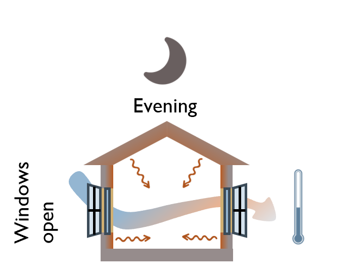

Night-time ventilation
Heat absorbed by building surfaces through the day is radiated inside as long-wave infrared even after the sun sets. Since ambient temperatures at night can be lower than the indoor space temperatures, there is an opportunity to remove this heat build-up by opening windows and/or mechanically ventilating during night-time.
D
Climatic opportunities: Diurnal range and high intensity solar radiation
Climate Characteristics

Thermal mass
Building materials with high capacity to store heat, dampen the impact of external temperatures to maintain comfortable conditions indoors. Thermal mass is feasible when diurnal range or difference in daily maximum and minimum temperature exceeds 6°C. For cold climate, a time lag of around 8 hours brings in heat indoors at night when it is most required. Since roof absorbs the most radiation during day time, it plays a significant role in storing heat and radiating it inside during the night.
It is also advisable that a the surface finish is darker (with low albedo) to promote heat absorption and storage.
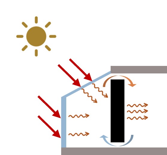
Solarium/sun-space
Geographies in cold climate are typically located in higher altitudes that see clear skies. This implies ample availability of high intensity solar radiation for heating.
A solarium/sun-space is essentially a glass enclosure that traps direct solar radiation as long-wave infrared during the sunshine hours. This is further used to heat a dark coloured absorptive surface with heavy thermal mass. This surface absorbs heats up during the day and emits heat during night to provide relief from cold.
Sun-spaces are effective when they receive unhindered direct solar radiation and should therefore be planned on the south side.
D
Climatic opportunity: Diurnal range and night-sky cooling
Climate Characteristics
Thermal mass
Building materials with high capacity to store heat, dampen the impact of external temperatures to maintain comfortable condition indoors. Thermal mass is feasible when diurnal range or difference in daily maximum and minimum temperature exceeds 6°C.

Courtyard cooling
Courtyards have the potential to enhance ventilation and promote indoor comfort. For effectively regulating indoor temperature, the courtyards must be shaded. In addition, incorporating landscape and water elements can improve their ability to cool. Water features act as heat sinks and promote evaporative cooling. Courtyards are central to cluster planning approach. IS 13727:1993 prescribes, (a) minimum courtyard width of 6m or 3/4th building height, (b) the maximum width of 13m, and, (c) courtyard area exceeding 36m2.
D Climatic opportunities Climate Characteristics
From a thermal comfort point of view, the human body finds it difficult to reject heat in a warm-humid environment as there is negligible difference between the air and skin temperature. Therefore the opportunities for achieving comfort are limited to allowing breeze to not only pass through the window but also across the body surface of the occupants. To improve the effectiveness of ventilation, other strategies to avoid solar gains must be adopted as well. Judicious use of shading and low thermal mass in structure can complement natural ventilation,
Enhanced natural ventilation
Almost constant wind direction is a characteristic feature of warm-humid climate and this can be leveraged to enhance natural ventilation.
- Aligning building openings to prevailing wind direction (see D).
- Larger window-openings may be required for enhanced ventilation
- Since, by nature, warm-humid climate is endemic to coastal areas there is potential to leverage sea-breeze that flows from sea to land during the day and in the opposite direction during the night. Sea breeze is significant until 100 km from the coastline.
Due care must be taken while sizing and orienting windows. While windows can enhance ventilation they can bring in heat too.
Shaded windows with shutters
While this isn’t a climatic opportunity, it complements enhanced natural ventilation by limiting solar gains.
Owing to cloud cover, there is significant diffused radiation implying the requirement for adequate and practical shading.
- Shading has its limitations and must be augmented with external movable shutters that can cut-off all radiation when not desirable while still allowing ventilation. External shutters with venetian blinds are one example of external movable shades that cut-off radiation while still allowing ventilation.
 Low thermal mass
Since day-night temperature difference is marginal, it becomes difficult to expel the heat trapped in the structure throughout the day. Low thermal mass avoids this build-up. The breeze flowing through the built mass in turn has to carry away lesser heat from the built mass.
D
Climatic opportunities: Diurnal range and night-sky cooling
Climate Characteristics
Thermal mass
Building materials with high capacity to store heat, dampen the impact of external temperatures to maintain comfortable condition indoors. Thermal mass is feasible when diurnal range or difference in daily maximum and minimum temperature exceeds 6°C.
Night-time ventilation
Heat absorbed by building surfaces through the day is radiated inside as long-wave infrared even after the sun sets. Since ambient temperatures at night can be lower than the indoor space temperatures, there is an opportunity to remove this heat build-up by opening windows and/or mechanically ventilating during night-time.
A Site context: Microclimate, siting & orientation Passive Design

Weather data for site location
Identify periods of year the building is likely to experience discomfort. Prioritize passive solutions for these time periods. (See climate section.)
Sun path and solar radiation analyses
Perform sun-path studies of existing context (including trees) to identify solar access on site. This can be useful in identifying buildable zones, and shaping building form.
Wind analysis
Wind studies (based on predominant wind direction during discomfort periods) can be used to identify natural ventilation potential of the site.
B1 Mitigating urban heat islands – reflective roof & wall surfaces Passive Design
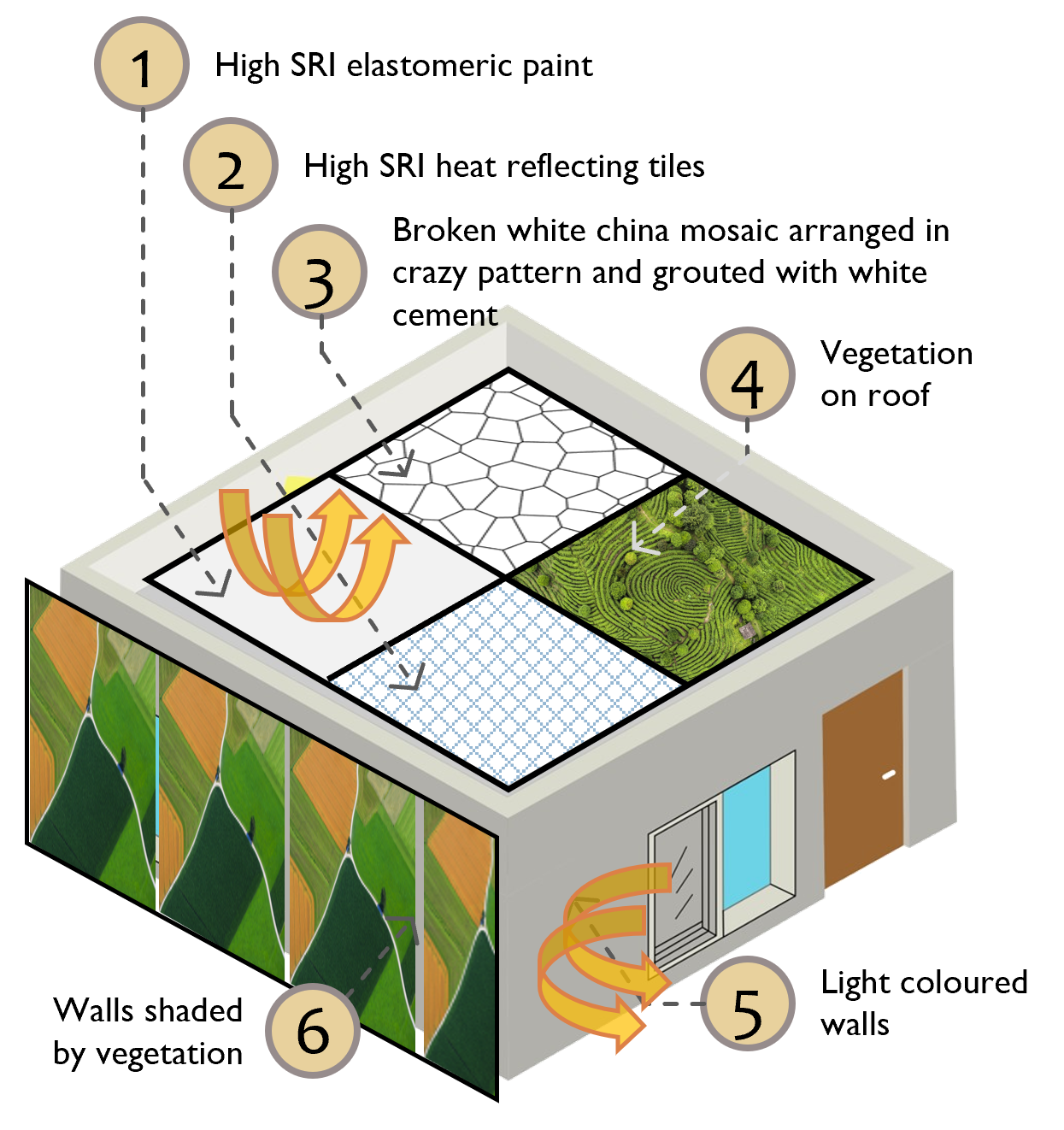
Cool Roofs and Cool Walls
Reflective and emitting exterior surfaces have the potential of reducing surface temperatures by 4-5°C. This in turn can reduce the amount of heat being transferred to indoor spaces. This can also enhance the overall microclimate by mitigating urban heat islands.
Exposed roof surfaces may be treated with either:
- High SRI elastomeric paint
- Heat reflecting tiles
- Broken white china mosaic grouted with white cement
- Vegetation on walls and roof surfaces have an effect similar to reflective and emitting surfaces. Landscaping uses soil media which has the potential of providing insulation as well.
Exposed wall surfaces may be painted with heat reflective paints.
B1 Absorptive roof and wall surfaces Passive Design

Absorptive Roofs and Walls
Dark coloured (or absorptive surface) that have high thermal inertia can raise internal temperatures by 3°C. This in turn can stave off cold discomfort.
Absorptive surfaces (i.e. low albedo value) and low emittance have the potential to store more heat during the day-time and transfer stored heat during the night-time.
B2 Mitigating urban heat islands – reducing paved surfaces Passive Design


Reduce hard paved areas
Replace hard paved areas with landscape as much as possible
Shade paved areas
Plan paved areas such that they are shaded by buildings or vegetation for most parts of the day. Cover paved areas with temporary structures.
Use reflective and emitting surfaces for pavements
Provide at least 50% of hard paved areas with materials having SRI 50 or greater.
B2 Landscape for thermal comfort in cold climates Passive Design

Colder climate in India is typically restricted to high altitudes. The tree ecosystem in these hilly regions, especially the Himalayas, is of paramount significance. Not only do these serve as carbon sinks, but they are also key in maintaining the structural integrity of the terrain.
Judicious planning of trees plays a key role in improving thermal comfort. In extreme cold weather, hill slopes often experience a rapid descent of cold dense air, also known as katabatic winds. Tree clusters have the potential to act as a barrier and provide protection to the down-wind residential development.
Owing to high intensity radiation, dwellings in colder regions can experience overheating during summers. Deciduous tree species with their dense foliage, have the ability to provide shade in summers (when there is overheating risk). In winters these tree species shed their leaves and allowing sunlight through to protect from cold discomfort.
B3 Mitigating urban heat islands – minimum tree Cover Passive Design

Trees moderate the microclimate by reflecting radiation, evapotranspiration and by providing shade. This leads to reduction in ambient temperatures and overall improvement in thermal comfort.

Tree canopy area requirements
Maintaining a minimum tree canopy area (x) can mitigate urban heat islands. For fulfilling tree canopy area requirements, the landscape design must consider native tree species that mature to a height (y) of 6 ft (or 2m) or greater. Trees with high foliage density should be preferred as they provide shade. Some native tree species are identified in B3-1.
While a higher tree canopy is desirable, it may lead to high humidity that could adversely impact thermal comfort outcomes. Similarly, while high foliage density is desirable, its impact on the built environment during winter months must be taken into account. Due care must be practiced while selecting tree species
B3 Maintaining minimum tree cover Passive Design
Trees moderate the microclimate by reflecting radiation, evapotranspiration and by providing shade. They can also provide barrier to cold winds. This can facilitate favourable microclimate for achievement of thermal comfort.
Tree canopy area requirements
Maintaining a minimum tree canopy area (x) can mitigate urban heat islands. For fulfilling tree canopy area requirements, the landscape design must consider native tree species that mature to a height (y) of 6 ft (or 2m) or greater. Trees with high foliage density should be preferred as they provide shade. Some native tree species are identified in B3-1.
While a higher tree canopy is desirable, it may lead to high humidity that could adversely impact thermal comfort outcomes. Similarly, while high foliage density is desirable, its impact on the built environment during winter months must be taken into account. Due care must be practiced while selecting tree species
B3 1. Tree canopy area of common Indian trees Passive Design

Neem (Azadirachta Indica)
Crown Dia: 10-20m
Tree Height: 15-30m

Gulmohar (Delonix Regia)
Crown Dia: 8-12m
Tree Height: 15-20m

Mango (Mangifera Indica)
Crown Dia: 15-20m
Tree Height: 35-40m

Pipal (Ficus Religiosa)
Crown Dia: 10-15m
Tree Height: 8-15m

Indian Almond Tree (Terminalia Catappa)
Crown Dia: 10-15m
Tree Height: 15-23m

Arjuna Tree (Terminalia Arjuna)
Crown Dia: 15-23m
Tree Height: 15m

Golden-Shower (Cassia Fistula )
Crown Dia: 8-10m
Tree Height: 8-15m

Banyan (Ficus Benghalensis)
Crown Dia: 23m
Tree Height: 15m

Pride of India (Lagerstroemia Speciosa)
Crown Dia: 15-23m
Tree Height: 10-15m

Dense Foliage

Medium-dense Foliage

Light-dense Foliage
B3 1. Tree canopy area of common Indian trees Passive Design

Aralu (Ailanthus Glandulosa)
Crown Dia : 2.5 to 9.6 m
Height at Maturity: 4.3 to 14 m

Teak (Tectona grandis)
Crown Dia : 10 to 11 m
Height at Maturity: 13 to 45 m

Mango Tree-(Mangifera Indica)
Crown Dia: 15-20m
Height at Maturity: 35 to 40 m

Jangli Toot / Paper Mulberry (Broussonetia Papyrifera)
Crown Dia : 8 to 10 m
Height at Maturity: 6 to 18 m

Indian Horse-chestnut (Aesculus Indica)
Crown Dia: 10-15m
Height at Maturity: 15 to 23 m

Devdar (Cedrus deodara)
Crown Dia: 6 to 14 m
Height at Maturity: 15 to 25 m

Himalayan poplar (Populus ciliate)
Crown Dia: 3 to 5 m
Height at Maturity: 18 to 24 m

Chinar Tree (Platanus Orientalis)
Crown Dia: 15 to 21 m
Height at Maturity: 21 to 30 m

Himalayan birch (Betula utilis)
Crown Dia: 5 to 8 m
Height at Maturity: 8 to 15 m

Dense Foliage

Medium-dense Foliage

Light-dense Foliage
C Opening ratios for regulating ventilation & heat gains Passive Design

Operable window area ratio
At least 1/8th of window area serving habitable spaces should be openable. This will ensure all habitable spaces are adequately ventilated.
Windows serving habitable spaces must open to the exteriors.

Window to wall area ratio
No wall should have window exceeding 1/4th of its area.
Large windows have the potential to cause hot pockets within a room due to direct radiation

Operable window to wall area ratio
Overall window opening area should not exceed 40% of overall carpet area. Limiting glazing area avoids excessive heat gains and losses in the space.
C Opening ratios for regulating ventilation & heat gains Passive Design

Operable window area ratio
At least 1/12th of window area serving habitable spaces should be openable. This will ensure all habitable spaces are adequately ventilated.
Windows serving habitable spaces must open to the exteriors.
Window to wall area ratio
No wall should have window exceeding 1/4th of its area.
Large windows have the potential to cause hot pockets within a room due to direct radiation
Operable window to wall area ratio
Overall window opening area should not exceed 40% of overall carpet area. Limiting glazing area avoids excessive heat gains and losses in the space.
C Opening ratios for regulating ventilation & heat gains Passive Design

Operable window area ratio
At least 1/10th of window area serving habitable spaces should be openable. This will ensure all habitable spaces are adequately ventilated.
Windows serving habitable spaces must open to the exteriors.
Window to wall area ratio
No wall should have window exceeding 1/4th of its area.
Large windows have the potential to cause hot pockets within a room due to direct radiation
Operable window to wall area ratio
Overall window opening area should not exceed 40% of overall carpet area. Limiting glazing area avoids excessive heat gains and losses in the space.
C Opening ratios for regulating ventilation & heat gains Passive Design

Operable window area ratio
At least 1/6th of window area serving habitable spaces should be openable. This will ensure all habitable spaces are adequately ventilated.
Windows serving habitable spaces must open to the exteriors.
Window to wall area ratio
No wall should have window exceeding 1/4th of its area.
Large windows have the potential to cause hot pockets within a room due to direct radiation
Operable window to wall area ratio
Overall window opening area should not exceed 40% of overall carpet area. Limiting glazing area avoids excessive heat gains and losses in the space.
D Window openings for enhanced ventilation Passive Design

Window orientation
Windows facing the windward side function as air inlets. Orient inlet windows within 30° of the prevalent wind direction to maximize the effectiveness of natural ventilation.

Window size distribution
Inlet windows shall be equal to or larger than the outlet windows to enhance air movement within the indoor space.

Window cill height
Window cill height at 0.75 m is ideal for the seated position. Judicious planning of window heights enables air movement in the occupied zone.

Level A
Single-sided ventilation
A window placed on a single external wall provides ventilation and, access to daylight and views. It is necessary that this window opening is unobstructed.
Compared to no windows, a single window provides significant improvement to quality of space.

Level A+
Single sided ventilation: Openings distributed on a single side
Distributing windows on single side not only improves ventilation performance, but also daylight performance.

Level A++
Two (or more)-sided ventilation: Windows on adjacent walls
Placing windows on two or more walls improves ventilation performance compared to single-sided ventilation, Further, placing windows diagonally across is expected to provide best ventilation performance.
D Window openings for enhanced ventilation Passive Design
Window orientation
Windows facing the windward side function as air inlets. Orient inlet windows within 30° of the prevalent wind direction to maximize the effectiveness of natural ventilation.
Window size distribution
Inlet windows shall be equal to or larger than the outlet windows to enhance air movement within the indoor space.
Window cill height
Window cill height at 0.75 m is ideal for the seated position. Judicious planning of window heights enables air movement in the occupied zone.
Level A
Single-sided ventilation
A window placed on a single external wall provides ventilation and, access to daylight and views. It is necessary that this window opening is unobstructed.
Compared to no windows, a single window provides significant improvement to quality of space.
Level A+
Single sided ventilation: Openings distributed on a single side
Distributing windows on single side not only improves ventilation performance, but also daylight performance.
Level A++
Two (or more)-sided ventilation: Windows on adjacent walls
Placing windows on two or more walls improves ventilation performance compared to single-sided ventilation, Further, placing windows diagonally across is expected to provide best ventilation performance.
Note: Typically, window operation for natural ventilation in cold climate will be restricted to short periods. In Cold climate, the intent is to harvest solar gains to stave off cold discomfort. In summer, however, harvesting solar gains may lead to overheating. Natural ventilation then comes in handy to expel the unwanted gains. Due care must be taken to properly seal windows.
E Window shading for limiting thermal gains Passive Design

Designing for shading – When to shade?
Design for shades whenever ambient temperature exceeds 28°C and global horizontal radiation exceeds 315 kWh/m2.
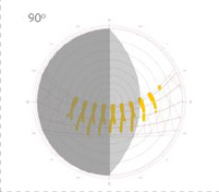
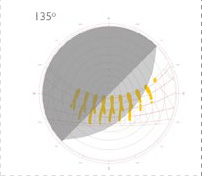
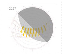
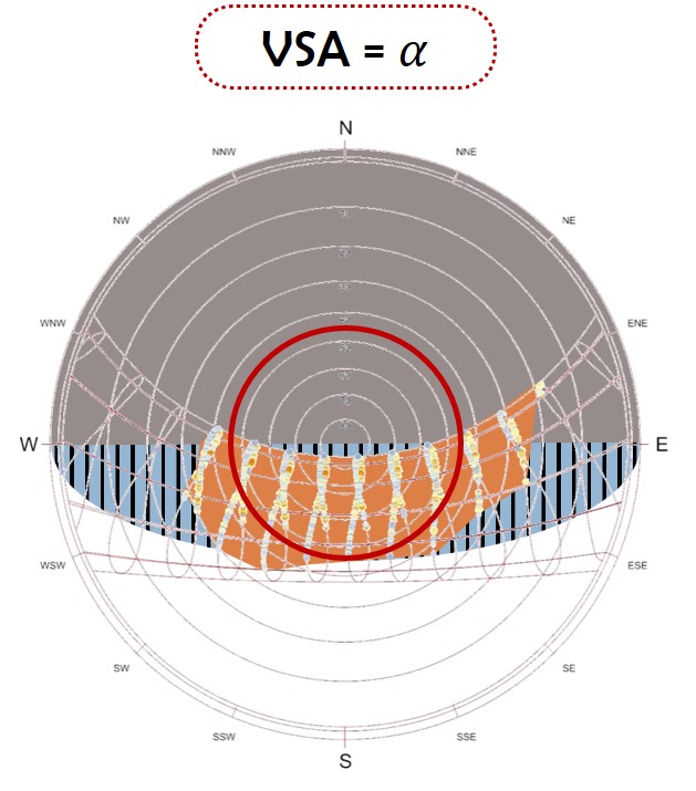
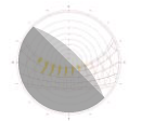
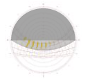
A stereographic chart is a useful tool for superimposing solar path and weather data to identify time of the year when shading is required.


Designing for shading – How to shade?
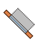
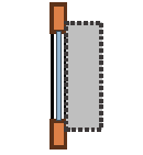
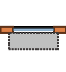
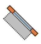
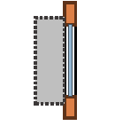
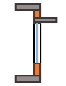
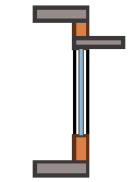
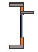
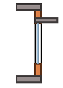
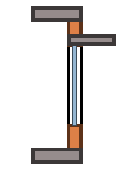
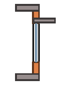
Read projection factors for your climate and latitude from the Shading factor tables. While shading is the primary defense against solar gains, it may not be practical to design a single shade. Take cues from the image above on distributing overhangs and fins into multiple elements (while maintain the projection factor) for designing practical shading devices.
Overhang Projection Factor
Projection factor or (PF) is the ratio of the depth of the overhang (i.e. D) to the distance of cill from the base of the overhang (i.e. H).
Fin Projection Factor
Projection factor or (PF) is the ratio of the depth of the fin (i.e. D) to the distance of the furthermost edge of the window from the base of the fin (i.e. H).
| Orientation | 0° | 45° | 90° | 135° | 180° | 225° | 270° | 315° | ||||||||
|---|---|---|---|---|---|---|---|---|---|---|---|---|---|---|---|---|
| Shade type | O-H | Fin | O-H | Fin | O-H | Fin | O-H | Fin | O-H | Fin | O-H | Fin | O-H | Fin | O-H | Fin |
| Either | Either | Either | ||||||||||||||
| Projection Factors | 0.47 | L-0.18 | 1.00 | - | 1.00 | - | 1.00 | - | 1.00 | - | 1.00 | - | 1.00 | - | 1.00 | L-1.00 |
| R-0.18 | R-1.00 | - | - | - | - | - | - | |||||||||
| Shadow mask |  |
 |
 |
 |
 |
 |
 |
 |
||||||||
| Section through window – Plan view |
 |
|
|
|
|
|
|
|
||||||||
| Section through window- Elevation view | 
|
 |
 |
|
|
|
|
|
||||||||
| Orientation | 0° | 45° | 90° | 135° | 180° | 225° | 270° | 315° | ||||||||
|---|---|---|---|---|---|---|---|---|---|---|---|---|---|---|---|---|
| Shade type | O-H | Fin | O-H | Fin | O-H | Fin | O-H | Fin | O-H | Fin | O-H | Fin | O-H | Fin | O-H | Fin |
| Either | Either | Either | ||||||||||||||
| Projection Factors | 0.47 | L-0.18 | 1.00 | - | 1.00 | - | 1.00 | - | 1.00 | - | 1.00 | - | 1.00 | - | 1.00 | - |
| R-0.36 | - | - | - | - | - | - | R-1.00 | |||||||||
| Shadow mask | 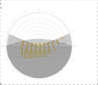 |
 |
 |
 |
 |
 |
 |
 |
||||||||
| Section through window – Plan view | |
|
|
|
|
|
|
|
||||||||
| Section through window- Elevation view | 
|
|
|
|
|
|
|
|
||||||||
E Window shading for limiting thermal gains Passive Design
Designing for shading – When to shade?
Design for shades whenever ambient temperature exceeds 28°C and global horizontal radiation exceeds 315 kWh/m2.
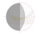
A stereographic chart is a useful tool for superimposing solar path and weather data to identify time of the year when shading is required.

Designing for shading – How to shade?
Read projection factors for your climate and latitude from the Shading factor tables. While shading is the primary defense against solar gains, it may not be practical to design a single shade. Take cues from the image above on distributing overhangs and fins into multiple elements (while maintain the projection factor) for designing practical shading devices.
Overhang Projection Factor
Projection factor or (PF) is the ratio of the depth of the overhang (i.e. D) to the distance of cill from the base of the overhang (i.e. H).
Fin Projection Factor
Projection factor or (PF) is the ratio of the depth of the fin (i.e. D) to the distance of the furthermost edge of the window from the base of the fin (i.e. H).
| Orientation | 0° | 45° | 90° | 135° | 180° | 225° | 270° | 315° | ||||||||
|---|---|---|---|---|---|---|---|---|---|---|---|---|---|---|---|---|
| Shade type | O-H | Fin | O-H | Fin | O-H | Fin | O-H | Fin | O-H | Fin | O-H | Fin | O-H | Fin | O-H | Fin |
| Projection Factors | L-0.18 | 0.47 | - | 0.84 | - | 0.70 | - | 0.70 | - | 1.00 | - | 1.00 | - | 1.00 | - | |
| - | - | - | - | - | - | - | - | |||||||||
| Shadow mask | 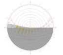 |
 |
 |
 |
 |
 |
 |
 |
||||||||
| Section through window – Plan view |  |
 |
 |
 |
 |
 |
 |
 |
||||||||
| Section through window- Elevation view | 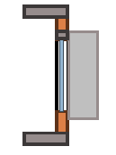 |
 |
 |
 |
 |
 |
 |
 |
||||||||
Note:
1. External movable shades are not required for buildings in cold climate.
2. Shading factors have been developed for cities above 23.5° N only due to unavailability of weather files for latitudes below 23.5° N. In absence of weather files below 23.5° N, same shading factors may be applied.
E Window shading for limiting thermal gains Passive Design
Designing for shading – When to shade?
Design for shades whenever ambient temperature exceeds 28°C and global horizontal radiation exceeds 315 kWh/m2.
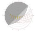
A stereographic chart is a useful tool for superimposing solar path and weather data to identify time of the year when shading is required.
Designing for shading – How to shade?
Read projection factors for your climate and latitude from the Shading factor tables. While shading is the primary defense against solar gains, it may not be practical to design a single shade. Take cues from the image above on distributing overhangs and fins into multiple elements (while maintain the projection factor) for designing practical shading devices.
Overhang Projection Factor
Projection factor or (PF) is the ratio of the depth of the overhang (i.e. D) to the distance of cill from the base of the overhang (i.e. H).
Fin Projection Factor
Projection factor or (PF) is the ratio of the depth of the fin (i.e. D) to the distance of the furthermost edge of the window from the base of the fin (i.e. H).
| Orientation | 0° | 45° | 90° | 135° | 180° | 225° | 270° | 315° | ||||||||
|---|---|---|---|---|---|---|---|---|---|---|---|---|---|---|---|---|
| Shade type | O-H | Fin | O-H | Fin | O-H | Fin | O-H | Fin | O-H | Fin | O-H | Fin | O-H | Fin | O-H | Fin |
| Projection Factors | 0.47 | L-0.36 | 1.00 | - | 0.84 | - | 0.84 | - | 0.84 | - | 1.00 | - | 1.00 | - | 1.00 | - |
| =0.36 | - | - | - | - | - | - | - | |||||||||
| Shadow mask | |
|
|
|
|
|
|
|
||||||||
| Section through window – Plan view |
|
|
|
|
|
|
|
|
||||||||
| Section through window- Elevation view |
|
|
|
|
|
|
|
|
||||||||
Note:
1. External movable shades are not required for buildings in cold climate.
2. Shading factors have been developed for cities above 23.5° N only due to unavailability of weather files for latitudes below 23.5° N. In absence of weather files below 23.5° N, same shading factors may be applied.
F1 Key performance parameters: Opaque assemblies – Wall & Roof Passive Design

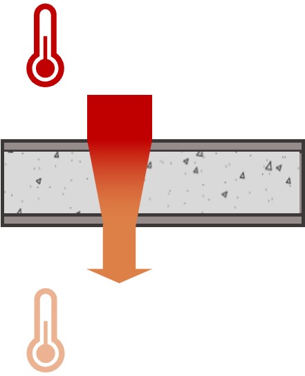
Thermal Conductance (U-factor)
U-factor of an opaque construction assembly is a measure of heat conducted through a unit area of material for 1°C temperature difference.
ISO 6946 provides method for testing thermally homogeneous (including assemblies with air layers) assemblies. It also provides an approximate method for evaluating inhomogeneous layers.


Reflectance & Emittance
As solar radiation strikes an opaque surface, a part of it gets absorbed, while the rest gets reflected. The portion absorbed by the surface is ‘emitted’ out as long-wave infra-red radiation. The reflected component is termed as ‘Reflectance’ and the emitted component is termed as ‘Emittance’. Both are expressed as a ratio between 0 and 1.
For external wall surfaces, the test procedures for evaluating reflectance and emittance are detailed out in Wall Product Rating Program Manual CRRC-2.


Solar Reflective Index (SRI)
Solar reflective index is a metric that combines the effect of a material’s ability to reflect incident solar radiation as well as its ability to emit thermal radiation.
The SRI value of a product shall be tested as per ASTM E 1980. This standard defines the method to determine the solar reflectance, the thermal emittance and the subsequent calculation for SRI.
F2 Key performance parameters: Transparent Assemblies - Glazing Passive Design

Thermal Conductance (U-factor)
The thermal conductance of glass is the amount of non-solar heat (i.e. heat flow via conduction and convection) transmitted through a glazing of unit area for 1°C temperature difference.
U-factor may also be used to represent the thermal conductance across a glazing construction assembly, i.e. glass along with frame, spacer material and other components.
Solar Heat Gain Coefficient(SHGC)
SHGC is a measure of heat transmitted through the glazing via radiation. It is a unitless metric and expressed as a number between 0 and 1.
SHGC is the fraction of solar heat gain radiated through the glazing either directly or after absorption.
Visible Light Transmittance(VLT)
VLT is a measure of light entering into the space through the glazing. It is a unitless metric and expressed as a number between 0 and 1.
VLT is the fraction of light in the visible spectrum transmitted through the glass. VLT is arrived at after weighting for sensitivity of the human eye.
Performance tests for U-factor, SHGC and VLT for glazing and glazing assemblies(U-factor)
ISO-9050 provides methods for testing glass for, U-factor, Solar Heat Gain Coefficient (SHGC) and Visible Light Transmittance (VLT).
ISO 12576-1 provides test methods for testing complete glazing construction assemblies, i.e. glass along with frame, sash, shutter, etc. for U-factor, SHGC and VLT.
G1 Key performance requirements: Opaque assemblies – Wall & Roof Passive Design


| Light-weight assembly | Medium/Heavy-weight assembly | ||
|---|---|---|---|
| Density (kg/m3) | >=800 | <800 | |
Level A |
0.80 | 1.00 or lower | |
Level A+ |
0.60 | 0.80 or lower | |
Level A++ |
0.40 | 0.45 or lower | |
Reflectance 0.60 or higher
Emittance 0.75 or higher
SRI 29 or higher

Level A
0.75 or lower
Level A+
0.45 or lower
 Level A++
0.25 or lower
Level A++
0.25 or lower

Reflectance 0.70 or higher
Emittance 0.75 or higher
SRI 78 or higher
G1 Performance requirements: Opaque assemblies-Wall & Roof Passive Design
| Light-weight assembly | Medium/Heavy-weight assembly | ||
|---|---|---|---|
Density (kg/m3) |
>=800 | <800 | |
Level A |
0.80 | 0.85 or lower | |
Level A+ |
0.60 | 0.50 or lower | |
Level A++ |
0.35 | 0.35 or lower | |
Level A
0.75 or lower
Level A+
0.45 or lower
Level A++
0.25 or lower
G1 Key performance requirements: Opaque assemblies-Wall & Roof Passive Design
| Light-weight assembly | Medium/Heavy-weight assembly | ||
|---|---|---|---|
| Density (kg/m3) | >=800 | <800 | |
Level A/A+ |
0.80 | 1.00 or lower | |
Level A++ |
0.40 | 0.45 or lower | |
Reflectance 0.60 or higher
Emittance 0.75 or higher
SRI 29 or higher
Level A
0.75 or lower
Level A+
0.45 or lower
Level A++
0.25 or lower
Reflectance 0.70 or higher
Emittance 0.75 or higher
SRI 78 or higher
G2 Key performance requirements: Glazing assembly Passive Design

Level A
U-factor 5.7 or lower
SHGC 0.6 or lower
VLT 0.3 or higher
Level A+
U-factor 4.8 or lower
SHGC 0.4 or lower
VLT 0.3 or higher
Level A++
U-factor 2.8 or lower
SHGC 0.4 or lower
VLT 0.3 or higher


Windows are a potential thermal bridge, i.e. source of uncontrolled thermal exchange between the indoor space and the external environment. In naturally ventilated buildings, metal frame with thermal break, wooden and vinyl window frames minimize bridging losses. In air-conditioned buildings, it is especially important to eliminate thermal bridges to minimize cooling/heating losses. Wood and vinyl are preferred in conditioned buildings as these are relatively less conducting. For all frame types, weatherstripping between sash and window frame, and caulk between window frame and structure are essential to effectively seal the windows and reduce uncontrolled air leakage.
G2 Key performance requirements: Glazing assembly Passive Design
Level A
U-factor 3.8 or lower
SHGC 0.7 or lower
VLT 0.3 or higher
Level A+
U-factor 2.8 or lower
SHGC 0.6 or lower
VLT 0.3 or higher
Level A++
U-factor 1.8 or lower
SHGC 0.6 or lower
VLT 0.3 or higher
Windows are a potential thermal bridge, i.e. source of uncontrolled thermal exchange between the indoor space and the external environment. In air-conditioned buildings, it is especially important to eliminate thermal bridges to minimize cooling/heating losses.
Wood and vinyl are preferred glazing assemblies as these are relatively less conducting. For all frame types, weatherstripping between sash and window frame, and caulk between window frame and structure are essential to effectively seal the windows and reduce uncontrolled air leakage.
H1 Performance bundles – Wall Passive Design
 Low Density
AAC Block Wall

- Exterior paint
- External cement plaster (GI chicken wire mesh over block-work and structure joints)
- AAC block work
- Internal cement plaster
- Interior paint
AAC Block work 200 mm
230 mm thick
0.78 W/m2K
AAC Block work 300 mm
330 mm thick
0.55 W/m2K
AAC Block Wall with external insulation

- Exterior paint
- Cement plaster/base Coat (over reinforcing mesh)
- Rigid insulation board applied with water based adhesive and held in place with PVC fasteners
- AAC block work
- Internal plaster (GI chicken wire mesh over block-work and structure joints)
- Interior paint
AAC Block work 150 mm
XPS/PUF 50 mm
230 mm thick ~0.34 W/m2K
 Medium Density
Fly ash brick wall with external insulation

- Exterior paint
- Cement plaster/base Coat (over reinforcing mesh)
- Rigid insulation board applied with adhesive and held in place with PVC fasteners
- Fly-ash block work
- Internal plaster
- Interior paint
Fly ash brick 230 mm
Expanded Polystyrene 25 mm
285 mm thick
0.89 W/m2K
Fly ash brick 230 mm
XPS/PUF 25 mm
285 mm thick
~0.75 W/m2K
Fly ash brick 230 mm
XPS/PUF 25 mm
315 mm thick
~0.55 W/m2K
Fly ash brick wall faced with AAC block outside

- Exterior paint
- Cement plaster/base coat (over reinforcing mesh)
- Rigid insulation board applied with water based adhesive and held in place with PVC fasteners
- Solid concrete block work
- Internal plaster
- Interior paint
Fly ash brick 115 mm
AAC block 150 mm
295 mm thick
0.88 W/m2K
Fly ash brick 75 mm
AAC block 200 mm
305 mm thick
0.73 W/m2K
 High Density
Solid concrete block with external insulation

- Exterior paint
- Cement plaster
- AAC block work
- Fly-ash block work
- Internal plaster
- Interior paint
Solid concrte block 200 m
Extruded Polystyrene 25 mm
255 mm thick ~0.81 W/m2K
Solid concrte block 200 m
Polyurethane Foam 25 mm
255 mm thick ~0.77 W/m2K
Solid concrte block 200 m
XPS/PUF 50 mm
285 mm thick ~0.45 W/m2K
H1 Performance bundles – Wall Passive Design
Low Density
AAC Block Wall
- Exterior paint
- External cement plaster (GI chicken wire mesh over block-work and structure joints)
- AAC block work
- Internal cement plaster
- Interior paint
AAC Block work 200 mm
230 mm thick
0.78 W/m2K
AAC Block work 300 mm
330 mm thick
0.55 W/m2K
AAC Block Wall with internal insulation

- Exterior finish (as/design)
- External cement plaster (GI chicken wire mesh over blockwork and structure joints)
- AAC block work
- Rigid insulation board applied with water based adhesive and held in place with PVC fasteners
- Vapour barrier (polythene sheet or any other suitable material)
- Gypsum plasterboard
- Interior Paint
AAC Block work 150 mm
XPS/PUF 50 mm
230 mm thick
~0.34 W/m2K
Medium Density
Fly ash brick wall with internal insulation

- Exterior paint
- Cement plaster/base Coat (over reinforcing mesh)
- Rigid insulation board applied with adhesive and held in place with PVC fasteners
- Cement plaster (for smooth finish to aid adhesion with rigid insulation board)
- Fly-ash block work
- Internal plaster
- Interior paint
Fly ash brick 230 mm
XPS/PUF 25 mm
285 mm thick ~0.75 W/m2K
Fly ash brick 230 mm
XPS/PUF 50 mm
315 mm thick ~0.45 W/m2K
Fly ash brick 230 mm
XPS/PUF 75 mm
335 mm thick ~0.31 W/m2K
Fly ash brick wall faced with AAC block outside

- Exterior paint
- Cement plaster
- AAC Block Work
- Fly ash block work
- Internal plaster
- Interior paint
Fly ash brick 75 mm
AAC block 200 mm
305 mm thic ~0.73 W/m2K
High Density
Solid concrete block with internal insulation

- Exterior paint
- External Cement plaster
- Solid Concrete Block
- Rigid insulation board applied with water based adhesive and held in place with PVC fasteners
- Vapour barrier (polythene sheet or any other suitable material)
- Gypsum plasterboard
- Interior paint
Solid concrete block 200 mm
XPS/PUF 25 mm
255 mm thick ~0.81 W/m2K
Solid concrete block 200 mm
XPS/PUF 50 mm
285 mm thick ~0.45 W/m2K
Solid concrete block 200 mm
XPS/PUF 25 mm
285 mm thick ~0.31 W/m2K
H1 Performance bundles – Wall Passive Design
Low Density
AAC Block Wall
- Exterior paint
- External cement plaster (GI chicken wire mesh over block-work and structure joints)
- AAC block work
- Internal cement plaster
- Interior paint
AAC Block work 200 mm
230 mm thick
0.78 W/m2K
AAC Block work 300 mm
330 mm thick
0.55 W/m2K
AAC Block Wall with external insulation
- Exterior paint
- Cement plaster/base Coat (over reinforcing mesh)
- Rigid insulation board applied with water based adhesive and held in place with PVC fasteners
- AAC block work
- Internal plaster (GI chicken wire mesh over block-work and structure joints)
- Interior paint
AAC Block work 150 mm
XPS/PUF 50 mm
230 mm thick ~0.34 W/m2K
Medium Density
Fly ash brick wall with external insulation
- Exterior paint
- Cement plaster/base Coat (over reinforcing mesh)
- Rigid insulation board applied with adhesive and held in place with PVC fasteners
- Fly-ash block work
- Internal plaster
- Interior paint
Fly ash brick 230 mm
Expanded Polystyrene 25 mm
285 mm thick
0.89 W/m2K
Fly ash brick 230 mm
XPS/PUF 25 mm
285 mm thick
~0.75 W/m2K
Fly ash brick 230 mm
XPS/PUF 25 mm
315 mm thick ~0.45 W/m2K
Fly ash brick wall faced with AAC block outside
- Exterior paint
- Cement plaster
- AAC block work
- Fly ash block work
- Internal plaster
- Interior paint
Fly ash brick 115 mm
AAC block 150 mm
295 mm thick
0.88 W/m2K
Fly ash brick 75 mm
AAC block 200 mm
305 mm thick
0.73 W/m2K
High Density
Solid concrete block with external insulation
- Exterior paint
- Cement plaster/base coat (over reinforcing mesh)
- Rigid insulation board applied with water based adhesive and held in place with PVC fasteners
- Solid concrete block work
- Internal plaster
- Interior paint
Solid concrte block 200 m
Extruded Polystyrene 25 mm
255 mm thick ~0.81 W/m2K
Solid concrte block 200 m
Polyurethane Foam 25 mm
255 mm thick ~0.77 W/m2K
Solid concrte block 200 m
XPS/PUF 50 mm
285 mm thick ~0.45 W/m2K
H1 Performance bundles – Wall Passive Design
Low Density
AAC Block Wall
- Exterior paint
- External cement plaster (GI chicken wire mesh over block-work and structure joints)
- AAC block work
- Internal cement plaster
- Interior paint
AAC Block work 200 mm
230 mm thick
0.78 W/m2K
AAC Block work 300 mm
330 mm thick
0.55 W/m2K
AAC Block Wall with external insulation
- Exterior paint
- Cement plaster/base Coat (over reinforcing mesh)
- Rigid insulation board applied with water based adhesive and held in place with PVC fasteners
- AAC block work
- Internal plaster (GI chicken wire mesh over block-work and structure joints)
- Interior paint
AAC Block work 150 mm
XPS/PUF 50 mm
230 mm thick ~0.34 W/m2K
Medium Density
Fly ash brick wall with external insulation
- Exterior paint
- Cement plaster/base Coat (over reinforcing mesh)
- Rigid insulation board applied with adhesive and held in place with PVC fasteners
- Fly-ash block work
- Internal plaster
- Interior paint
Fly ash brick 230 mm
Expanded Polystyrene 25 mm
285 mm thick
0.89 W/m2K
Fly ash brick 230 mm
XPS/PUF 25 mm
285 mm thick
~0.75 W/m2K
Fly ash brick 230 mm
XPS/PUF 25 mm
315 mm thick ~0.45 W/m2K
Fly ash brick wall faced with AAC block outside

- Exterior paint
- Cement plaster
- AAC block work
- Fly ash block work
- Internal plaster
- Interior paint
Fly ash brick 115 mm
AAC block 150 mm
295 mm thick
0.88 W/m2K
Fly ash brick 75 mm
AAC block 200 mm
305 mm thick
0.73 W/m2K
High Density
Solid concrete block with external insulation
- Exterior paint
- Cement plaster/base coat (over reinforcing mesh)
- Rigid insulation board applied with water based adhesive and held in place with PVC fasteners
- Solid concrete block work
- Internal plaster
- Interior paint
Solid concrete block 200 m
Extruded Polystyrene 25 mm
255 mm thick ~0.81 W/m2K
Solid concrete block 200 m
Polyurethane Foam 25 mm
255 mm thick ~0.77 W/m2K
Solid concrete block 200 m
XPS/PUF 50 mm
285 mm thick ~0.45 W/m2K
H2 Performance bundles – Roof Passive Design
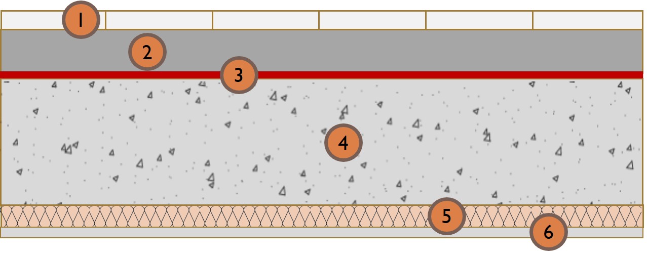
Foam concrete insulation over RCC slab. Roof assembly finished with broken white china mosaic.

- Broken china mosaic (white tiles grouted with white cement) applied with cement mortar
- Plain Cement Concrete (PCC) screed laid to slope
- Foam concrete
- Waterproofing layer
- Reinforced Cement Concrete (RCC) slab (as/structural design)
- Internal plaster
Foam concrete 75 mm
RCC slab as/design
~280 mm thick
~0.73 W/m2K
Foam concrete 150 mm
RCC slab as/design
~355 mm thick
~0.41 W/m2K
Rigid foam insulation over RCC slab. Roof assembly finished with broken white china mosaic.

- Broken china mosaic (white tiles grouted with white cement) applied with cement mortar
- Water proofing layer
- Cement screed with welded mesh
- Polythene sheet/Geo-textile membrane
- Rigid insulation board applied with water-based adhesive
- Brick-bats/Plain Cement Concrete (PCC) laid to slope
- RCC slab (as/structural design)
- Internal plaster
PUF/XPS 25 mm
RCC slab as/design
~280 mm thick
~0.73 W/m2K
PUF/XPS 50 mm
RCC slab as/design
~305 mm thick
~0.45 W/m2K
PUF/XPS 75 mm
Foam Concrete 100mm*
RCC slab as/design
~305 mm thick
~0.45 W/m2K
H2 Performance bundles – Roof Passive Design
Foam concrete insulation over RCC slab. Roof assembly finished with broken white china mosaic.
- Broken china mosaic (white tiles grouted with white cement) applied with cement mortar
- Plain Cement Concrete (PCC) screed laid to slope
- Foam concrete
- Waterproofing layer
- Reinforced Cement Concrete (RCC) slab (as/structural design)
- Internal plaster
Foam concrete 75 mm
RCC slab as/design
~280 mm thick
~0.73 W/m2K
Foam concrete 150 mm
RCC slab as/design
~355 mm thick
~0.41 W/m2K
Rigid foam insulation over RCC slab. Roof assembly finished with broken white china mosaic.
- Broken china mosaic (white tiles grouted with white cement) applied with cement mortar
- Water proofing layer
- Cement screed with welded mesh
- Polythene sheet/Geo-textile membrane
- Rigid insulation board applied with water-based adhesive
- Brick-bats/Plain Cement Concrete (PCC) laid to slope
- RCC slab (as/structural design)
- Internal plaster
PUF/XPS 25 mm
RCC slab as/design
~280 mm thick
~0.73 W/m2K
PUF/XPS 50 mm
RCC slab as/design
~305 mm thick
~0.45 W/m2K
PUF/XPS 75 mm
Foam Concrete 100mm*
RCC slab as/design
~305 mm thick
~0.45 W/m2K
H2 Performance bundles – Roof Passive Design
Foam concrete insulation over RCC slab

- Tiles applied with cement mortar
- Plain Cement Concrete (PCC) screed laid to slope
- Foam concrete
- Waterproofing layer
- Reinforced Cement Concrete (RCC) slab (as/structural design)
- Internal plaster
Foam concrete 75 mm
RCC slab as/design
~280 mm thick
~0.73 W/m2K
Foam concrete 150 mm
RCC slab as/design
~355 mm thick
~0.41 W/m2K
Rigid foam insulation installed under RCC slab.
- Finishing surface (tiles, stone, etc.) applied over cement mortar
- Plain Cement Concrete (PCC) screed laid to slope
- Water proofing layer
- Reinforced Cement Concrete (RCC) slab (as/structural design) thoroughly cleaned of all dust, dirt and loose particles with wire brush
- Rigid insulation board applied with adhesive, held in place with screws and joints sealed with tape.
- Internal plaster applied over reinforcing mesh
PUF/XPS 25 mm
RCC slab as/design
~280 mm thick
~0.73 W/m2K
PUF/XPS 50 mm
RCC slab as/design
~305 mm thick
~0.45 W/m2K
PUF/XPS 75 mm
Foam Concrete 100mm*
RCC slab as/design
~305 mm thick
~0.45 W/m2K
Foam concrete insulation and rigid foam insulation installed under RCC slab.

- Finishing surface (tiles, stone, etc.) applied over cement mortar
- Plain Cement Concrete (PCC) screed laid to slope
- Water proofing layer
- Reinforced Cement Concrete (RCC) slab (as/structural design) thoroughly cleaned of all dust, dirt and loose particles with wire brush
- Rigid insulation board applied with adhesive, held in place with screws and joints sealed with tape.
- Internal plaster applied over reinforcing mesh
PUF/XPS 25 mm
RCC slab as/design
~330 mm thick
~0.73 W/m2K
PUF/XPS 50 mm
RCC slab as/design
~305 mm thick
~0.45 W/m2K
PUF/XPS 75 mm
Foam Concrete 100mm*
RCC slab as/design
~305 mm thick
~0.45 W/m2K
H3 High thermal performance bundles – Alternative materials for wall construction Passive Design
Level A++
Compressed Stabilised Earth Block
Rammed Earth
Autoclave Aerated Concrete Block
Fly Ash Brick


H3 High thermal performance bundles – Alternative materials for wall construction Passive Design
Level A++
Compressed Stabilised Earth Block
Rammed Earth
Autoclave Aerated Concrete Block
Fly Ash Brick
H4 High thermal performance bundles – Alternative materials for roof construction Passive Design
Level A++
Straw Thatch Roof

Level A++
Straw Thatch Roof with Coir Insulation

Level A++
Bamboo Mud Slab with Coir Insulation

Level A++
Green Roof with Coir Insulation

Level A+
Terracotta Tile RCC Filler Slab with Coir Insulation

Level A
Terracotta Tile RCC Filler Slab with Rice Husk Insulation

H4 High thermal performance bundles – Alternative materials for roof construction Passive Design
Level A++
Straw Thatch Roof
Level A++
Straw Thatch Roof with Coir Insulation
Level A++
Bamboo Mud Slab with Coir Insulation
Level A++
Green Roof with Coir Insulation
Level A+
Terracotta Tile RCC Filler Slab with Coir Insulation
Level A
Terracotta Tile RCC Filler Slab with Rice Husk Insulation
H5 Key material specifications Passive Design
ACC Block

 0.184
0.184
 642
642
Source: CBERD-MNRE
Rammed Earth Wall
 0.58
1,540
0.58
1,540
Source: Gupta P., et al.
Solid Concrete Block
 1.411
2,350
1.411
2,350
Source: SP-41
Fly Ash Brick
 0.856
1,650
0.856
1,650
Source: Gourav K., et al.
CSEB
 1.026
1,700
1.026
1,700
Source: Balaji N.C., et al.
Cellular/ Foam Concrete
 0.188
704
0.188
704
Source: SP-41
Burnt Clay Brick
 0.811
1,820
0.811
1,820
Source: SP-41
Adobe Block
 0.75
1,731
0.75
1,731
Source: SP-41 (Mud-brick)
Reinforced concrete
 1.580
2,288
1.580
2,288
Source: SP-41
PUF [Polu Urethane Foam]
0.026
38-42
ASHRAE Handbook (Fundamentals)
Jute Fibre
0.067
329
Source: SP-41
XPS [Extruded Poly-Styrene]
0.029
34-36
ASHRAE Handbook (Fundamentals)
Saw Dust
0.051
188
Source: SP-41
Rockwool (unbonded)
0.043
150
Source: SP-41
Rice Husk
0.051
120
Source: SP-41
Exterior Paint (Wall/Roof)

 >78
>78
Heat Reflective Tiles (Wall/Roof)
 >78
>78
White China Mosaic (Grouted in white cement)
 >78
>78
A1 Design recommendations for ceiling fans (size & numbers) Active Design
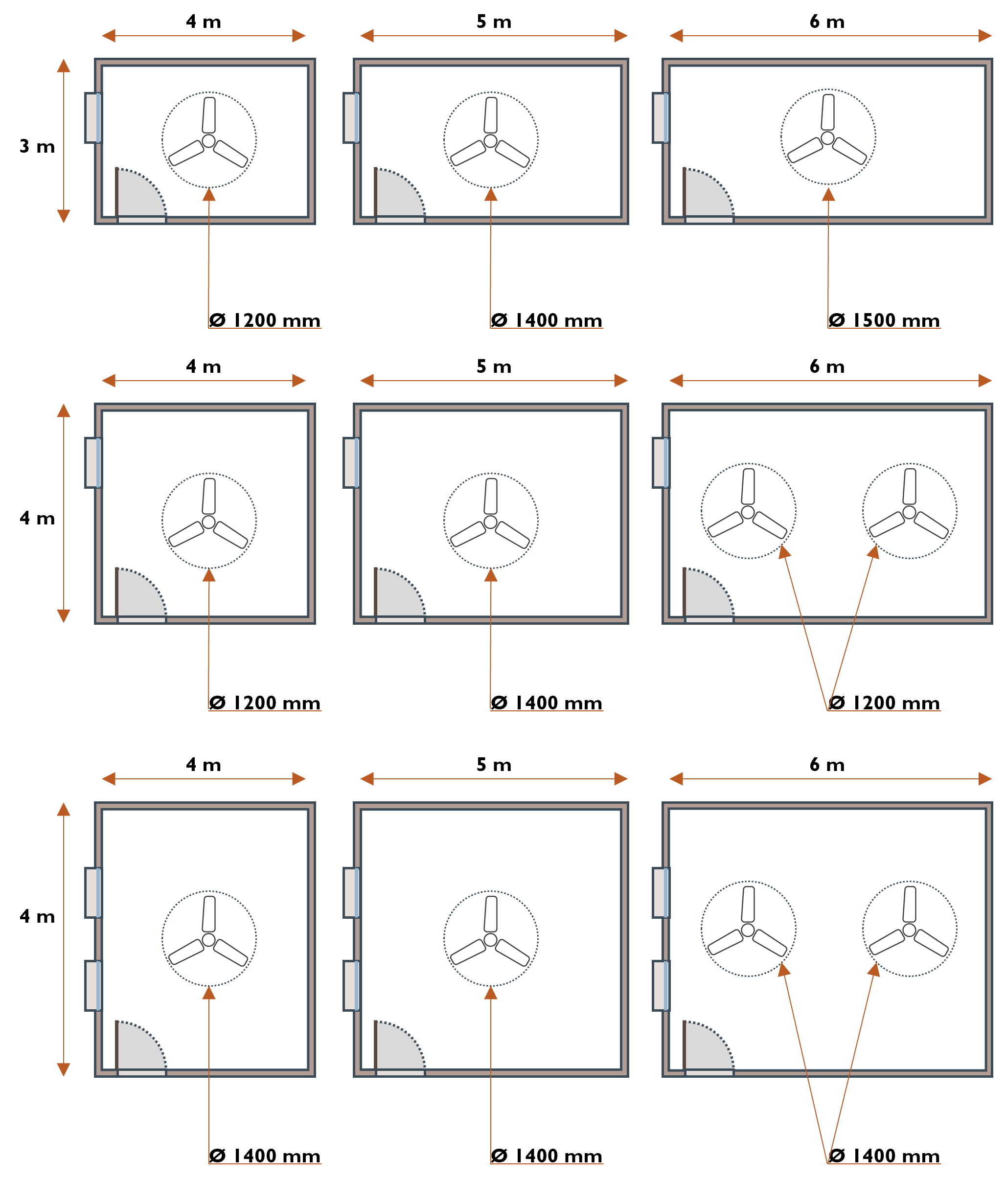
Source: SP-41
A2 Design recommendations for sizing desert coolers Active Design

 Space Volume
 (m3) |
 Fan Dia
 (mm) |
 Cooling Pad Area
 (m3) |
 Water Tank
 (liters) |
 Cooling Capacity
 (Tons) |
|---|---|---|---|---|
| 30-50 | 300 | 1.3 | 40 | 1.0 |
| 40-60 | 400 | 1.9 | 60 | 1.2 |
| 80-120 | 450 | 2.1 | 80 | 2.0 |
Source: SP-41 |
||||
The desert/swamp cooler is a cost-effective and energy efficient alternative for cooling during hot-dry periods. The cooling capacity of the desert cooler is dependent upon air flow and effective area for heat exchange. Cooling efficiency is expressed as

Tdb is is dry bulb temperature at the inlet, Tdb’ is dry bulb temperature at the outlet and Twb is the wet bulb temperature at the inlet.
A3 Design recommendations for exhaust fans in kitchen, bath and lavatories Active Design

All kitchen, bath and lavatory spaces must maintain minimum ventilation to maintain health and hygiene. These spaces shall have provision to directly exhaust air outside.
B Star labelled equipment and minimum efficiencies Active Design


C1 Low-energy systems: Evaporative cooling Active Design

Direct evaporative cooling
Water has high heat capacity and can readily absorb heat from the ambient air. Evaporation implies water changes its state from liquid to vapor. This change of state is an energy intensive process. In this case the heat energy held by the air during hot-dry conditions is consumed in the evaporation process leading to cool air.

Desert/Swamp coolers
Desert/Swamp coolers provide effective cooling during summer using this principle. A powerful exhaust fan draws in hot-dry air from the outside. This air passes over wet filter media losing its heat in the process. The same exhaust fan delivers this cool air indoors.

Downdraught systems
Vertical ventilation shafts funnel in ambient hot-dry air from the top . This hot-dry air is evaporatively cooled. The cooler air, laden with humidity is denser and starts sinking in the vertical shaft. This downward draught of cooler air can be channeled through spaces for cooling. This technique is not only helpful for cooling air, but also for enhancing ventilation performance, more so when it is aided with mechanical ventilation systems. Passive downdraught systems are especially useful during hot-dry conditions.
C1 Low-energy systems: Evaporative cooling Active Design
Direct evaporative cooling
Water has high heat capacity and can readily absorb heat from the ambient air. Evaporation implies water changes its state from liquid to vapor. This change of state is an energy intensive process. In this case the heat energy held by the air during hot-dry conditions is consumed in the evaporation process leading to cool air.
Desert/Swamp coolers
Desert/Swamp coolers provide effective cooling during summer using this principle. A powerful exhaust fan draws in hot-dry air from the outside. This air passes over wet filter media losing its heat in the process. The same exhaust fan delivers this cool air indoors.
C2 Low-energy systems: Indirect evaporative cooling Active Design
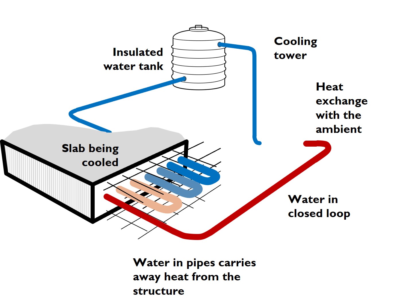
Structure cooling system
The structure of the building is often heavy thermal mass. This thermal mass has the capacity to absorb and retain heat for long periods. The retained heat is released indoors causing discomfort during summer months.
Structure cooling system embeds a network of pipes through the structural system. This network of pipes carries cool water that draws heat from the structure. This pipe carrying warm water (or heat from the structure) exits the structure and expels the heat outside to an air or water medium (cooling tower in the schematic here). The water in closed loop keeps cycling through the structure till there is heat is to be removed.
C3 Low-energy systems: Earth-to-air heat exchange Active Design
Earth-air tunnel
Sub-surface temperatures beyond 3m depth, tend to hover around the annual mean temperature. This provides an opportunity to exchange heat with ambient air (in both winters and summers) for achieving thermal comfort indoors.
Summer operation
Hot ambient air is drawn in via fans and pushed through an underground tunnel. As the air passes through the underground tunnel, it releases its heat to the cooler earth encasing the tunnel. This cooled air is pumped through a vertical shaft into warmer indoor spaces.

C4 Geo-thermal heat-pump coupled with radiant heating Active Design

A geothermal heat-pump (or ground source heat pump) coupled with structure embedded distribution system for radiant heating has 3 key components,
- the ground loop,
- the heat pump, and,
- hot-water distribution system embedded in the structure.
This system delivers efficiency on 3 counts, energy efficient heating technology, passive heating through geothermal principles, and efficient heat distribution systems.
Pre-heated water from ground loop feeds into the heat –pump thereby reducing the load on the heat pump. This heating load is further reduced as the heat is delivered through a radiant slab which does not require achieving temperatures as high as required by other conventional heating systems.
Typically the pipes for ground loop are buried vertically. For residential projects where land is available, the ground loop pipes can be laid horizontally underground (in slinky configuration upto 2m depth) as well.